Allen-Bradley DF1 Half Duplex Tag-Base Control/CompactLogix) Setup |
Topic: CM020 |
The following information applies to Allen-Bradley Control/CompactLogix PLC to set up using DF1 Half Duplex Tag-Based Serial.
The C-more panel is the master by default.
|
|
Note: For additional information on the Tags used for Allen-Bradley Tag-Based protocols, see Allen-Bradley Control/CompactLogix Tags. |

Setup a DF1 Half-Duplex Tag-Based PLC
To Setup a Tag Based DF1 (Half Duplex) to Control/CompactLogix PLC, match the Communication Parameters.
- This Controller Properties window opens.
- Click on the Serial Port Tab to display the items on the figure shown above.
- Set the following Parameters:
- When all of the above are complete, click on the System Protocol Tab.
- The Controller Properties window will now look like the figure shown below.
|
|
Note: If you are using DF1 Half Duplex (DF1 Slave in PLC), you must match the Station Address to the PLC Address in the C-more Panel Manager. Also match the Error Detection to the Checksum Type in the C-more Panel Manager. |
- From the Protocol field, choose the appropriate Protocol. For DF1 Half Duplex, choose DF1 Slave.
- If using DF1 Half Duplex (DF1 Slave in PLC), then you must match the Station Address to the PLC Address in the C-more Panel Manager. Also be sure to match the Error Detection to the Checksum Type in the C-more Panel Manager.
- Leave ALL other fields as shown above.
C-more Protocol Manager Settings
- Do one of the following:
- Click the Protocol Manager button on the Home tab
— or — - Click the Protocol Manager button on the Setup tab
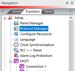
— or — - from the Navigation window, click the Function tab, click Setup and then select Protocol Manager.
- From the Protocol Manager window, click the Device name on the tree to the left.
- The Device Setup window opens.
When you select a different PLC Protocol than the one currently in use, the warning Message shown below appears.
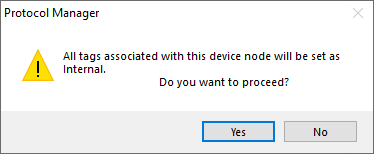
- Click Yes to accept.
Configure the C-more Panel Manager
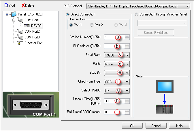
The C-more Panel Manager Configuration fields for the Allen-Bradley DF1 Full Duplex Tag-Based protocol for Control/CompactLogix is shown above.
The following are the parameters available for configuration:
- Station Number (0-254): The Station Number is the Slave Number or Address. This is the Number that will be polled by the Master (C-more panel) on the network. Address slaves from 1 through 254 for Modbus protocol, depending on the Slave and what CPU is used.
- PLC Address (0-254): The PLC Address is the Number or Address of the PLC communicating to the Panel. Typically this is 1 for the first PLC in the network. PLC can be addressed from 1 through 254.
- Baud Rate: The Baud Rate is the rate at which Data transmits across the connection in Bits Per Second (bps). A good starting point is 9600 bps. If no problems arise, then increase the Baud Rate to the maximum achievable without communication problems.
- Parity: Parity is a low level form of error checking that counts the number of 1 in the Bit Stream to ensure that none are different. The Parity Bit is configured to achieve the correct number of 1 in the Data packet; either Odd or Even. If the number of 1 is Even when parity is set to Odd, then the packet has been corrupted. This setting is set to Odd by default and should not require adjustment.
- Stop Bit: Stop Bit is an extra Bit that follows the Data and Parity Bits to mark the End of the transmission. For older systems, you can increase the Stop Bit to 2, but 1 is usually the correct setting. This setting is set to 1 by default and should not require adjustment.
- Checksum Type: The Checksum is a character positioned at the end of a Data block to detect any possible errors. Click the down arrow for these two options:
- BCC: Stands for Block-Check character and consists of an Error Detection method that places a character at the end of the Data block that is equal to the binary Sum of all the characters in the specific Data block and enables a check of Data accuracy after receiving the Data block across a network.
- CRC: Stands for Cyclic Redundancy Check and consists of an Error Detection method that treats all the characters in a message as a string of bits that represent a binary number. This binary number is inserted in the message to enable a check of Data accuracy after receiving the message across a network. CRC is the default for this field and should not require adjustment.
- Select RS485: Used when the C-more Panel is communicating to a device using RS-485. When used, the Control RTS setting is forced to Yes for controlling the RS-485 driver.
- Timeout Time (1-255) [100ms]: Enter a number that represents a time (in Tenths of a Second) that the C-more Panel waits for communications with the PLC before displaying an error. This setting is set to 30 Tenths of a Second by default, which is the same as 3 seconds and should not require any adjustment.
- Poll Time: Enter a number that represents a Time (in milliseconds) that the C-more Panel will wait between executing a complete sequence of reads for the screen displayed. This setting is set to "0" by default, which produces constant polling. This setting should not require adjustment.
Connection Through Another Panel
You can configure this protocol for any PLC supported by C-more panels.
You can connect a C-more panel to other C-more panels on your network via an ethernet connection. This type of connection is also known as a Pass Through Connection.
Go to Connection Through Another Panel (Pass-Through) to learn more about Pass Through and using Connection Through Another Panel.
