Allen-Bradley SLC 5/03, /04, /05 & MicroLogix 1000, 1100, 1200, 1400 and 1500 DF1 (Half Duplex) Protocol Setup |
Topic: CM001 |
The following information applies to Allen-Bradley SLC 5/03, /04, /05 & MicroLogix 1000, 1100, 1200, 1400, and 1500 PLC compatible with C-more panels using DF1 Half Duplex Protocol.
The C-more panel is the master by default.
C-more Protocol Manager Settings
- Do one of the following:
- Click the Protocol Manager button on the Home tab
— or — - Click the Protocol Manager button on the Setup tab
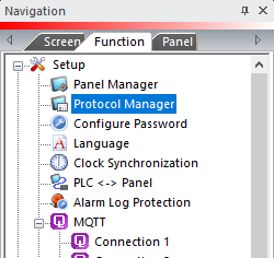
— or — - from the Navigation window, click the Function tab, click Setup and then select Protocol Manager.
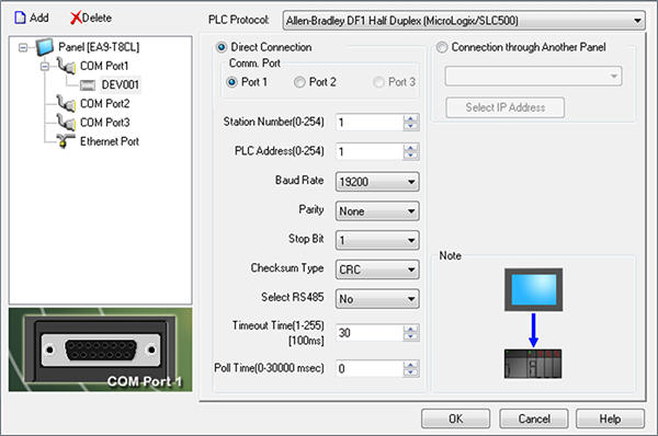
- From the Protocol Manager window, click the Device name on the tree to the left.
- The Device Setup window opens.
- From the PLC Protocol field, click on the down arrow
 and select Allen-Bradley DF1 Half Duplex (MicroLogix/SLC500).
When you select a different PLC Protocol than the one currently in use, the warning Message shown below appears.
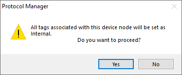
- Click Yes to accept.
Setup RSLogix 500
These settings must match the Protocol Manager in the C-more Programming Software.
To set up the RSLogix 500 for these PLC, follow these steps:
- In RSLogix 500, choose Channel Configuration in the left navigation window.
- From the Channel Configuration window shown below, choose the Channel 0-System tab.
|
|
Note: If you are using DF1 Half Duplex (DF1 Slave in PLC), then you must match the Station Address to the PLC Address in the C-more Protocol Manager. Also match the Error Detection to the Checksum Type in the C-more Panel Manager. |

- From this Configuration window, set the following:
- For the Driver field, select DF1 Half Duplex.
- For the Node Address, set the value to match the PLC Address in the C-more Protocol Manager window shown at the top of this page.
- For the Control Line field, choose No Handshaking.
- For the following fields, match the C-more Protocol Manager settings:
- Baud Rate
- Parity
- Stop Bits
- Error Detection (Checksum Type)

|
Caution: Record your PLC settings as you change them so that you can reconnect using the same settings later if needed. |
- Select OK from the Channel Configuration window.
- The warning window shown below appears.
- Choose Apply from this window and continue to next subject below.
PLC Address Configuration
There must be an address in the PLC for every address referenced in the C-more Project.
If a Numeric Display in C-more uses address C5:0.ACC, then C5:0.ACC must exist in the PLC Data Files. You can verify the address in the left side explorer window under Data Files.
- First, check for a file number (where 3 is the File Number for B3:0/0 and 7 is the file number for N7:0).
- Verify is that there are enough elements in the file.
- Right-click and choose Properties to verify that there is the proper number of elements in the file.
To create a new Data File:
- Right click on Data Files and choose New.
|
|
Note: You must be offline to do this. |
- The Create Data File window shown below opens.
- Enter the File Number you wish to use.
- Choose the Data Type.
- Choose the number of elements that you need.
- For B3:4/0, the 4 is the Element Number. This is also the same screen that you would use to increase the Number of Elements of an existing file.
- Select OK and download the changes to the processor.
Connection Through Another Panel
You can configure this protocol for any PLC supported by C-more panels.
You can connect a C-more panel to other C-more panels on your network via an ethernet connection. This type of connection is also known as a Pass Through Connection.
Go to Connection Through Another Panel (Pass-Through) to learn more about Pass Through and using Connection Through Another Panel.
Troubleshooting
Scenario
No communication between the panel and the PLC.
Most likely cause
Error Detection mismatch (called Checksum Type in the C-more Panel Manager).
Solution
Match the Error Detection.
Scenario
The C-more panel uses the same PLC port you use to connect your PC and RSLogix to the PLC.
Most likely cause
If you change settings for Protocol Manager or RSLogix, RSLogix may be able to reconnect.
Solution
Connect to the PLC through a different port if possible.
Consult your PLC representative for further help on this subject.
|
|
Caution: Record your PLC settings as you change them so that you can reconnect using the same settings later if needed. |
If your network returns communication errors, test the basic network setup:
Use a new project with :
- Matching PLC Port Settings (check with PLC programming software)
- Matching Protocol Manager settings
- A single Numeric Display object addressed to N7:0
- Transfer the new project.
- Power cycle the PLC.
- Power Cycle the Panel.
If your network continues to return communication errors:
- Power Cycle the Panel.
- Power cycle the PLC.
