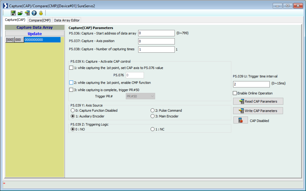
The Capture and Compare functions are for applications that require instant position records and the ability to compare positions, such as dynamic mark tracking (registration) or visual inspection. The Capture/Compare screen is divided into three tabs. Click the name of each tab below to jump to that section.
Capture (CAP)
Compare (CMP)
Data Array Editor

The Capture/Compare screen has a small toolbar with a handful of important functions.

| Button | Function |
|---|---|

|
Save as files
Save CAP and CMP parameter files in *.CAC format for later use. |

|
Open files
Open a previously created *.CAC file. |

|
Load from Servo
Copy CAP and CMP settings from the servo drive to the SureServo2 Pro software. |

|
Help
Opens the help file. |

|
Password Protection
Set up password protection. Set a password for the values in the CAP and CMP parameter file. This can be used to restrict changes to those with authorized access, and limit accidental changes. See below for setting a password. |
Password protection will lock chosen parameters and prevent them from being edited without using the set password. After clicking the Password Protection button on the toolbar, the following screen appears:
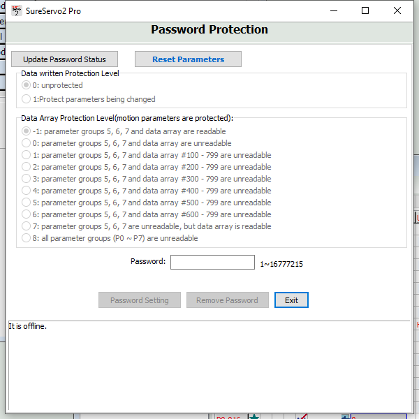
Use the radio buttons to set the protection status and parameter groups to be protected, then enter a password in the Password field and click Update Password Status. A password is now set for the chosen parameters groups.
The concept of Capture is to record the position of the motion axis instantly by using the external trigger signal DI7. This position is then saved in a data array to be used later for motion control. Since Capture is finished by hardware, there is no risk of software delay. It can also accurately capture the position of the high-speed motion axis. The Capture options provided by SureServo2 systems are:
| Option | Description |
|---|---|
| Pulse Source | Record with the main encoder of the motor, auxiliary encoder (linear scale), or Pulse command. The selected axis will be displayed in P5.037, the default value can be written in before capture. Note: When the source of compare is the CAP axis, the CAP source cannot be changed. |
| Trigger Signal | Triggered by DI7 with a response time of 5 µsec. Note that DI7 directly connects to the Capture hardware so can work regardless of the P2.016 (DI Code) setting. To avoid DI error, when performing a capture the system will force P2.016 to 0x0100 (disable) automatically. The value is not written to EEPROM and will reset to the previous value after re-powering the system. |
| Trigger Method | Edge trigger that can select contact A/B. The system can continuously capture more than one point. The interval between triggers can be set. |
| Data Storage Position | Stored in a data array. The start address is set by P5.036. |
| Capture Number | Set by P5.038, but will not exceed the limit of the data array. |
| Capture Format | 32-bit (has positive and negative) |
| Auxiliary Selection | After capturing the first data point, the CAP axis coordinate system will be set to the same value as P5.076 and the Compare function will be enabled. After capturing all desired points, PR #50 is triggered automatically. |
| DO.CAP_OK | This DO defaults to OFF. After capturing the last point, it switches to ON. Set P5.039.X0 to 1 to activate Capture and turn the DO to OFF. |
Note: If P5.038 = 0, setting the value of P5.039.X Bit0 to 1 will disable the Capture function. To clear the setting value of P5.039.X, change Bit0 to 0 and set DO.CAP_OK to OFF.
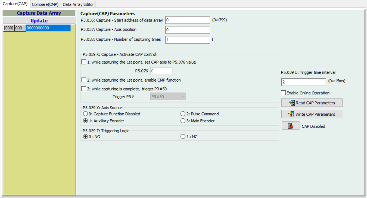
Configure the desired capture parameters using the Capture (CAP) window. Options on this screen are:
| Option | Function | ||||||||||
|---|---|---|---|---|---|---|---|---|---|---|---|
| Update | Copy the latest data from the servo drive to the software. | ||||||||||
| Capture - Start address of data array | P5.036 sets the address for the first capture value to be saved at. Default is 0, setting range is 0 to the value set by P5.010 minus 1. Please note that this parameter is only writable when Capture is disabled (P5.039.X bit 0 = 0). | ||||||||||
| Capture - Axis position | P5.037 displays the axis position of Capture pulse source. Please note that this parameter is only writable when Capture stops (please refer to P5.039). If the source is the main encoder, this parameter is write-protected and the Capture axis position is the feedback position of the motor (monitoring variable 00h). Default is 0, setting range is -2147483648 to +2147483647. | ||||||||||
| Capture - Number of capturing times | When Capture stops, P5.038 indicates the number of data elements in the array expected to be captured (readable and writable). When Capture activates, this parameter indicates the remaining number of data elements to be captured (read-only); each time an element is captured, the value of P5.038 decrements by one until the value is 0. Once P5.038 reaches 0 it indicates that the Capture Cycle is complete. Default is 0, setting range is 0 to the value set by P5.010 minus 1. Note that the total number of data elements from Compare, Capture, and E-Cam cannot exceed 800. | ||||||||||
| Capture - Activate CAP control | P5.039.X configures the capture setting:
|
||||||||||
| Axis Source | P5.039.Y configures the axis source of capture:
|
||||||||||
| Triggering Logic | P5.039.Z sets the triggering logic. 0=NO (normally open) while 1=NC (normally closed). | ||||||||||
| Trigger Time Interval | P5.039.U sets the minimum interval between triggers in milliseconds. | ||||||||||
| Enable Online Operation | Use this to simulate the action and make sure the settings will work properly. When the Enable Online Operation checkbox is checked the setting page will be locked by software to avoid errors during the test procedure. | ||||||||||
| Read CAP Parameters | Copy the CAP configuration parameters from the servo drive to the software. | ||||||||||
| Write CAP Parameters | Copy the CAP configuration parameters from the software to the servo drive. Note that if the start address for both Capture and Compare are the same, attempting to write will generate an error. | ||||||||||
| CAP Disabled | Displays the current Capture status. Clicking this button will change it to CAP Enabled and begin the Capture procedure. Click it again to return to the CAP Disabled status. |
The concept of Compare is to compare the current position of motion axis with the value saved in the data array, then output DO4 after the Compare condition is established for motion control. Since Compare is finished by hardware, there is no risk of software delay. It also can accurately compare position for the high-speed motion axis. The Compare options provided by SureServo2 servo drives are as follows:
| Option | Description |
|---|---|
| Pulse Source | Record with the main encoder of the motor, auxiliary encoder (linear scale), Pulse command, or CAP Axis (set by Capture). When CAP Axis is selected, the CAP source cannot be changed. The selected axis will be displayed in P5.057, the default value can be written in before compare. |
| Output Signal | Output by DO4 with a response time of 5 µsec. Note that DO4 directly connects to the Compare hardware so can work regardless of the P2.021 (DO Code) setting. To avoid DO error, when performing a compare the system will force P2.021 to 0x0100 (disable) automatically. The value is not written to EEPROM and will reset to the previous value after re-powering the system. |
| Output Method | Pulse output that can select contact A/B. The system can continuously output more than one point. The pulse output time can be set. |
| Data Storage Position | Stored in a data array. The start address is set by P5.056. |
| Compare Number | Set by P5.058, but will not exceed the limit of the data array. |
| Compare Format | 32-bit (has positive and negative) |
| Compare Condition | Compare will be triggered when the source of the compare axis passes through the compare value. |
| Auxiliary Selection | Cycle mode: when comparing to the last point, it automatically returns to the first point and starts to compare. When the last compare is completed, the Capture function is activated automatically. |
Note: If P5.058 = 0, setting the value of P5.059.X Bit0 to 1 will disable the Compare function. Change P5.059.X Bit0 to 0 to enable.
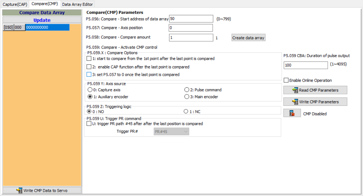
Configure the desired capture parameters using the Compare (CMP) window. Options on this screen are:
| Option | Function | ||||||||||
|---|---|---|---|---|---|---|---|---|---|---|---|
| Update | Copy the latest data from the servo drive to the software. | ||||||||||
| Compare- Start address of data array | P5.056 sets the address where the first Compare data is saved. Default is 0, setting range is 0 to the value set by P5.010 minus 1. Please note that this parameter is only writable when Compare stops (P5.059.X bit 0 = 0). | ||||||||||
| Compare- Axis position | P5.057 displays the axis position of Compare pulse source. Please note that this parameter is only writable when Compare stops (please refer to P5.059). If the source is the Capture axis, this parameter is write-protected. When the Compare axis source is the main encoder, P5.057 is also write-protected. The pulse resolution is determined by P1.046. When you set P5.059.Y to the main encoder, this parameter is set to the feedback position of the motor (monitoring variable 00h). When the motor feedback position is redefined due to homing or Capture, the value will be different from the parameter value. In this case, set P5.059.Y to 0, then set P5.059.Y to 3, to reset the parameter to the motor feedback position. Default is 0, setting range is -2147483648 to +2147483647. | ||||||||||
| Compare- Compare Amount | When Compare stops, P5.058 indicates the number of data elements in the array expected to be compared (read and write). When Compare activates, this parameter indicates the remaining number of data elements to be compared (read-only); each time an element is compared =, the value of P5.058 decrements by one until the value is 0. Once P5.058 reaches 0 it indicates that the Compare Cycle is complete. Default is 0, setting range is 0 to the value set by P5.010 minus 1. Note that the total number of data elements from Compare, Capture, and E-Cam cannot exceed 800. | ||||||||||
| Create Data Array | Used to create a data array of values to be compared. After setting the Compare Amount, a Data Array can be created with that many values. For example, if P5.058=20, Create Data Array will create an array with 20 entries. | ||||||||||
| Compare- Activate CMP control | P5.059.X configures the Compare setting:
|
||||||||||
| Axis Source | P5.059.Y configures the axis source of compare:
|
||||||||||
| Triggering Logic | P5.059.Z sets the triggering logic. 0=NO (normally open) while 1=NC (normally closed). | ||||||||||
| Trigger PR Command | P5.059.U sets the trigger PR. Currently the only valid value is 0 (Trigger PR). | ||||||||||
| Enable Online Operation | Use this to simulate the action and make sure the settings will work properly. When the Enable Online Operation checkbox is checked the setting page will be locked by software to avoid errors during the test procedure. | ||||||||||
| Read CMP Parameters | Copy the CMP configuration parameters from the servo drive to the software. | ||||||||||
| Write CMP Parameters | Copy the CMP configuration parameters from the software to the servo drive. Note that if the start address for both Capture and Compare are the same, attempting to write will generate an error. | ||||||||||
| CMP Disabled | Displays the current Compare status. Clicking this button will change it to CMP Enabled and begin the Compare procedure. Click it again to return to the CMP Disabled status. |
The Data Array Editor window is used to create and modify data arrays, as well as edit values stored in the array.
Save the captured data from Capture operations.
Save the compared value from Compare operations.
Save the contour table from E-Cam.
32-bit integer, up to 800 values (refer to P5.010)
Each entry has a corresponding address. The address must be specified when reading or writing the data.
Address range is from 000 to 799.
Manual setup of saving is required (P2.008=30,35) and data should be written to EEPROM of the servo drive.
Saves the data when the servo is OFF.
The data is loaded into the data array automatically when the servo is powered ON.
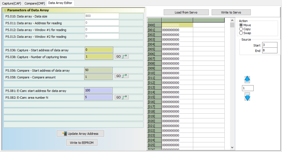
| Option | Function |
|---|---|
| Data array - Data Size | P5.010 displays the size of the data array. The default value is 800. This value is read-only. |
| Data array - Address for reading | P5.011 sets the address in the data array when reading and writing data. This value is read-only in the SureServo2 Pro software. P5.011 can be modified using MODBUS communications. |
| Data array - Window #1 for reading | P5.012 |
| Data array - Window #2 for reading | P5.013 |
| Capture - Start address of data array | P5.036 sets the address for the first capture value to be saved at. Default is 0, setting range is 0 to the value set by P5.010 minus 1. Please note that this parameter is only writable when Capture is disabled (P5.039.X bit 0 = 0). |
| Capture - Number of capturing times | When Capture stops, P5.038 indicates the number of data elements in the array expected to be captured (read and write). When Capture activates, this parameter indicates the remaining number of data elements to be captured (read-only); each time an element is captured, the value of P5.038 decrements by one until the value is 0. Once P5.038 reaches 0 it indicates that the Capture Cycle is complete. Default is 0, setting range is 0 to the value set by P5.010 minus 1. Note that the total number of data elements from Compare, Capture, and E-Cam cannot exceed 800. |
| Compare - Start address of data array | P5.056 sets the address where the first Compare data is saved. Default is 0, setting range is 0 to the value set by P5.010 minus 1. Please note that this parameter is only writable when Compare stops (P5.059.X bit 0 = 0). |
| Compare - Compare amount | When Compare stops, P5.058 indicates the number of data elements in the array expected to be compared (read and write). When Compare activates, this parameter indicates the remaining number of data elements to be compared (read-only); each time an element is compared =, the value of P5.058 decrements by one until the value is 0. Once P5.058 reaches 0 it indicates that the Compare Cycle is complete. Default is 0, setting range is 0 to the value set by P5.010 minus 1. Note that the total number of data elements from Compare, Capture, and E-Cam cannot exceed 800. |
| E-Cam: start address for data array | P5.081 sets the address for the first piece of data in the E-Cam table. This parameter is writable at any time, but is only effective when E-Cam status changes from pre-engaged to engaged. |
| E-Cam: area number N | P5.082 indicates that the E-Cam curve is divided into N segments, and the table includes N+1 data. This parameter is only writable when E-Cam stops (please refer to P5.088.X [Bit0] = 0). Its range must be smaller than or equal to P5.010 minus P5.081, and P5.082 x P5.084 must be smaller than or equal to 2147483647. Default value is 5, possible settings are 5 through 720. |
| GO | Clicking the GO button will jump to the start address for that function in the Data Array. For example, clicking GO next to the COMPARE values when P5.056 is set to 50 will jump to address 050 in the array. |
| Update Array Address | Copy the values of P5.036, P5.038, P5.056, P5.058, P50.81, and P5.082 from the software to the servo drive. |
| Write to EEPROM | Burn the values of P5.036, P5.038, P5.056, P5.058, P50.81, and P5.082 from the software to the servo drive EEPROM. This will preserve the settings through servo power OFF and restart. |
| Load From Servo | Copy Data Array values from the servo drive to the software. |
| Write to Servo | Copy Data Array values from the software to the servo drive. |
| Action | Use the radio button to set the action to be performed in the Data Array - Move, Copy, or Swap. Use Move to change the location of a value in the array. Use Copy to duplicate a value from one location to another. Use Swap to exchange the locations of values. |
| Source | Set the range of addresses on which to perform the selected action. For example, setting Source-Start to 3 and Source-End to 8 will perform the action on addresses 003 through 008. |
| Destination | For Copy and Swap actions, set the destination range of addresses here. Using the previous example, for a Copy setting Destination-Start to 13 and Destination-End to 18 would copy the values in addresses 003 through 008 to 013 through 018. |