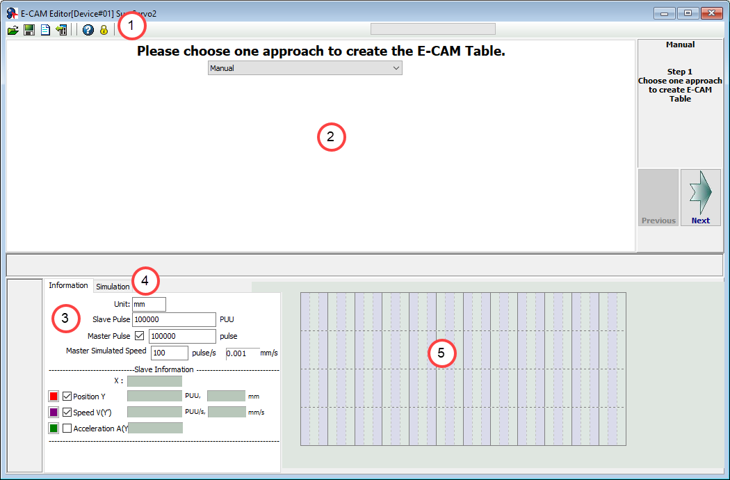
SureServo2 can use the built in E-Cam function to stabilize the control system and enable the servo drive to execute motion control command, such as synchronous conveyor, flying shear, and rotary cut. The main features of SureServo2's E-cam screen are:
Provides diversified Table Creating Wizard to easily complete each kind of E-Cam application.
720 points of E-Cam contour can be done via manual setting.
Parameter grouping: complete E-Cam setting without memorizing parameter number.
Provides E-Cam simulation so that users can simulate the E-Cam path.
The E-Cam screen can be broken down into several different sections.
1.) Toolbar - enables several important functions such as saving and loading E-Cam files. See Toolbar Overview for details.
2.) E-Cam table settings - used to create the E-Cam table. See Creating an E-Cam Table for details.
3.) Information tab - used to set master axis settings for use with the E-Cam table settings. The bottom half displays data points when mousing over the simulation graph.
4.) Simulation tab - used in conjunction with the Information tab, simulates master axis performance.
5.) Simulation sketch - displays a simulated E-Cam curve based on the software settings.
The toolbar contains several important functions for the E-Cam screen.
Button | Function |
---|---|
Open files
Open a previously created E-CAM file (*.ecd or *.ecm). |
|
Save as files
Save E-CAM file in *.ecd format for later use. |
|
New Edit
Restart configuration. Clicking this button will reset all settings in the E-CAM screen to default values. You will be prompted to confirm this choice - all unsaved changes will be lost. |
|
Load from Servo
Copy E-CAM settings from the servo drive to the SureServo2 Pro software. |
|
Help
Opens the help file. |
|
Password Protection
Set up password protection. Set a password for the values in the E-CAM parameter file. This can be used to restrict changes to those with authorized access, and limit accidental changes. |
Password protection will lock chosen parameters and prevent them from being edited without using the set password. After clicking the Password Protection button on the toolbar, the following screen appears:
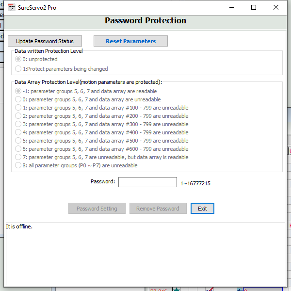
Use the radio buttons to set the protection status and parameter groups to be protected, then enter a password in the Password field and click Update Password Status. A password is now set for the chosen parameters groups.
The top window of the E-Cam Editor screen is used to configure the E-Cam table. To configure the table, follow the steps below:
Choose an approach for table creation from the drop down menu. Options are:
Manual
Speed Fitting
Rotary Shear w/o Sync Zone
Rotary Shear w/fixed Sync Zone
Rotary Shear w/adjustable Sync Zone
Cubic Curve
Rotary Shear - Printing Machine
The window will update once you've made a selection.
Click the Next button in the lower right corner of the E-Cam table settings window. This will take you to the first configuration window. Note that the contents of this window depend on the table approach chosen in Step 1. The example image below is for the Rotary Shear - Adjustable Sync Zone approach. Note that each approach has a different set of windows on this screen, but they all follow the same basic principles.
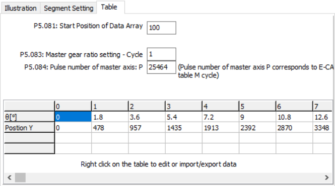
Configure the values as needed for your application in the main window (above) and click Create. This will generate a set of table values as shown in the example below. You can also import table data or edit the cells by right-clicking within the table.
It will also generate a simulation curve:
You can hover your mouse over the simulation curve to display precise values in the Slave Information section of this window.
To download table data to the servo drive, click Download Table (without persistent). This will copy the table data to the servo's memory, but it will be cleared when the servo powers OFF.
To burn the table data to the servo drive's EEPROM and make it available after power OFF and ON, click Make Table data in Servo be persistent.
Click Next to go to the Parameter Setup window. This window is the same for all table approaches.
Update the parameters as needed for your application, then click Download to copy them to the servo drive.
Option | Function |
---|---|
Engage (Entry Offset) | P5.085 sets the segment number of the E-Cam table when the E-Cam is engaged. Default is 0, range is 0 to the setting value of P5.082 minus 1. |
Master axis position | P5.086 sets the position counter of the E-Cam Master. This parameter is only writable when E-Cam stops (please refer to P5.088.X [Bit0] =0 in the SureServo2 User Manual). Default is 0, range is -2147483648 to +2147483647. |
Engage (lead pulse) | When the condition to engage E-Cam (P5.088.Z) is met, the pulse number from the master axis has to exceed the value of P5.087 (this parameter) for the E-Cam to fully engage. During this lead pulse period the drive is in a pre-engage state P5.088.D=2. This parameter can be written via virtual master pulse function (refer to description of P2.077). Default is 0, range is -1073741824 to +1073741823. |
Segment No. + (Polarity is Positive) | P5.090 - See the correlation between DO.CAM_Area and parameters in the figure below.
When E-Cam is disengaged, DO.CAM_Area is always off. Default is 270, range is 0-360. |
Area No. - (Polarity is Negative) | Please refer to P5.090 for the correlation between DO.CAM_Area and parameters. Default is 360, range is 0-360. |
E-Cam Curve Scaling | P5.019 - Use this parameter to magnify or reduce the magnitude of the E-Cam table without changing its value. Example: if the data in the table is 0, 10, 20, 30, 40, 20, then setting P5.019=2.000000 will cause the E-Cam table to run values 0, 20, 40, 60, 80. This enables the operation of E-Cam change amplitude with the same pulse frequency of the master axis. Magnification enlarges the path within the same time envelope and therefore proportionally increases the speed. Default is 1.000000, range is -2147.000000 to +2147.000000. |
Click Next to open the Engaging Conditions window. This window is the same for all table approaches.
Set the options as needed for your application, then click Download to copy the values to the servo drive.
Finally, click Enable E-CAM and ensure the drive is set to Servo ON for a trial run of the E-Cam.