The Analog I/O screen allows you to adjust a variety of settings related to command and monitoring inputs. These options are split between two tabs, detailed below.
You can load the current parameter values from the drive by clicking Read All Parameters. To copy all parameters on the screen to the drive, click Write All Parameters. To update just the parameters bounded by the blue box, click Write Selected Item(s). Note that for this section, the Speed Input and Torque Input tabs do not have sub-sections that can be selected, so both write options will copy all the parameters on those screens.
The Command Input tab is further subdivided into the Speed Input, Torque Input, and Position Input tabs. Click on the tab name for tab specific details. Note that some values will be grayed out and unavailable depending on the mode the drive is in (P1.001). Example: the Speed Input parameters will be unavailable if the drive is in PR Mode.
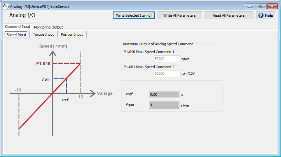
The Speed Input tab allows you to adjust the maximum speed commands as well as view servo system voltage and rpm values in real-time.
Option | Function |
---|---|
Maximum Speed Command 1 | P1.040 sets the maximum rotation speed corresponding to 10V (maximum voltage) for the analog speed command. The default is 3000rpm with possible settings from 0 to 50,000 rpm. |
Maximum Speed Command 2 | P1.081 also sets the maximum rotation speed corresponding to 10V (maximum voltage) for the analog speed command when DI.SPDKVC is ON. The Digital Input SPDKVC (0x0F) allows you to switch from using one analog input scaling to a second, independent analog input scaling. |
Vref | Displays the velocity reference value from the servo system in real time, in Volts. |
Vrpm | Displays the actual velocity of the motor in real time, in RPM. |
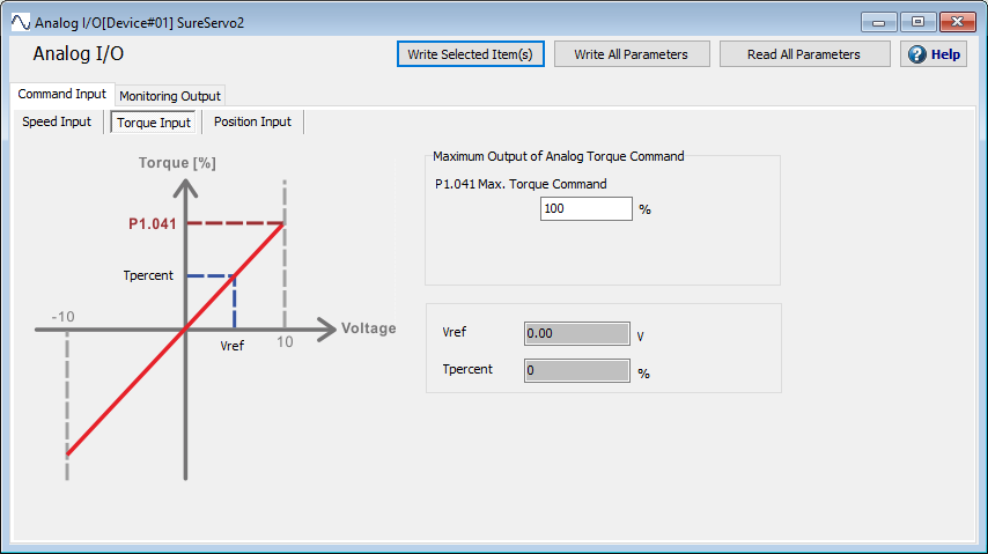
The Torque Input tab allows you to adjust the maximum torque command as well as monitor Vref and Tpercent in real time.
Option | Function |
---|---|
Maximum Torque Command | P1.041 sets the maximum output for the analog torque command. The default value is 100%, with settings ranging from -1000 to +1000 %. |
Vref | |
Tpercent | Displays the actual torque percentage of the motor in real time. |
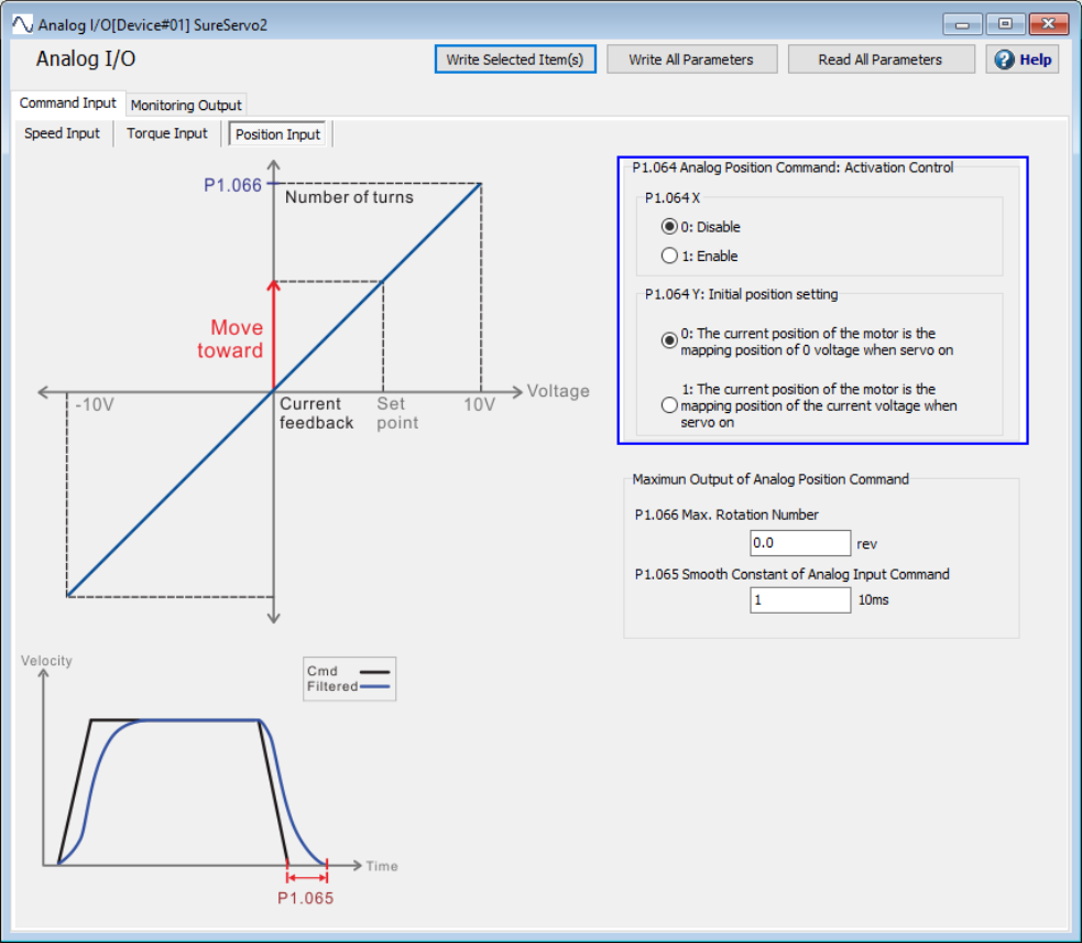
The Position Input tab allows you to adjust the analog position command, max rotation, and smooth constant. Analog Positioning is only available when the drive is set to PT Mode.
Option | Function |
---|---|
Analog Position Command: Activation Control - Polarity | P1.064.X enables or disables the position command being issued by the analog signal. A setting of 0 disables this option, a setting of 1 enables it. Analog Positioning is only available in PT Mode (P1.001). |
Analog Position Command: Activation Control - Initial Position Setting | P1.064.Y determines whether the motor treats the current position as the mapping position when the voltage is 0V or the mapping position for the current voltage. A setting of 0 tells the motor to use 0V, a setting of 1 tells the motor to use the current voltage. |
Maximum Rotation Number | P1.066 sets the maximum number of rotations when using maximum voltage (10V) with the analog position command. Lower input voltages will lower the maximum number of rotations proportionally. For example, a value of 3.0 gives +3 cycles at 10V. If the input is 5V, a value of 3.0 gives +1.5 cycles. The default value is 1.0 cycles, with settings ranging from 0.0 to 200.0 cycles. |
Smooth Constant of Analog Input Command | P1.065 sets the smooth constant for the analog position command (only). The default value is 1, possible settings are 1-1000 in increments of 10ms. |
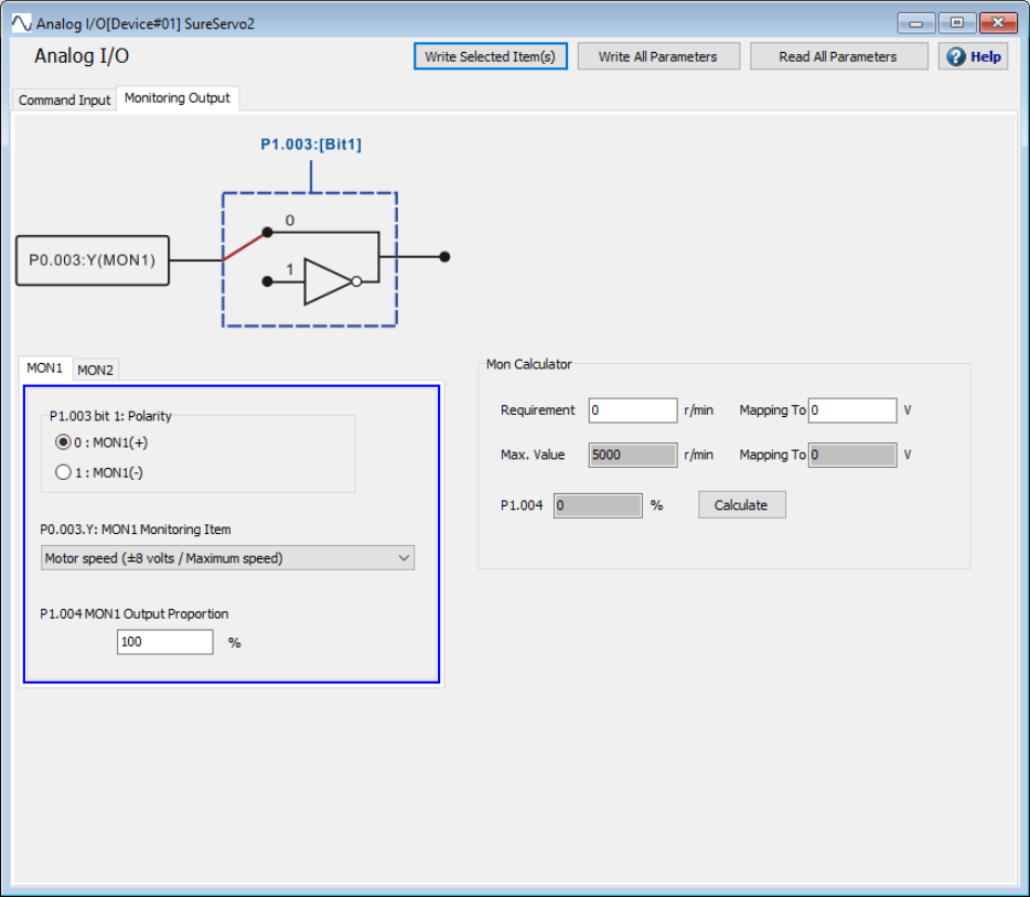
The Monitoring Output tab allows you to set the polarity, monitoring item, and output proportion for MON1 and MON2. The screen also includes a Mon Calculator that will take an RPM and voltage requirement and provide you the value you need to assign to P1.004.
To use the calculator, put your desired RPM in the Requirement box and the input voltage in the Mapping To box. Press the Calculate button to get a result in the calculator's P1.004 box or P1.005 for MON2. Note that the calculator's inputs and maximums will change based on your selection for P3.003.Y or P0.003.X for MON2.
Option | Function |
---|---|
Polarity | P1.003 bit 1 (for MON1) or P1.003 bit 0 (for MON2) set the polarity for MON1 and MON2. A value of 0 sets normal polarity while a value of 1 sets inverted polarity. |
Monitoring Item | P0.003.Y (for MON1) or P1.003.X (for MON2) sets the monitoring item via the drop down menu. Please see the SureServo2 User Manual for details on each option. |
Output Proportion | P1.004 (for MON1) or P1.005 (for MON2) set the analog monitor output proportion for MON1 and MON2. The default value is 100%, with possible settings from 0 to 100%. Use the Mon Calculator to help choose a value. |