|
|
Topic: P202 |
Logic Scan Behavior |
|
|
|
Topic: P202 |
Logic Scan Behavior |
|
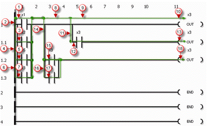
The Logic Scan Behavior of the Productivity Suite software will follow a consistent flow of operation.
Refer to the image below when following this Logic Scan example:
Rung 1 – Scan left to right and Update Output tag (Step 1), Drop to next rung (Step 2).
Rung 2 – Scan left to right (Step 3), Evaluate all branch circuits for power flow affecting Output and Update Output tag (Step 4), Drop to Sub-rung 2.1 (Step 5).
Rung 3 – Scan left to right and Update Output tag (Step 12).
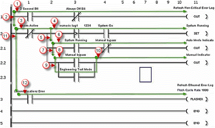
Refer to the image below when following this Logic Scan example:
Rung 1 – Scan left to right, Evaluate all branch circuits for power flow affecting Output (Steps 1-9), Update Output tag (Step 10), Drop down to first Sub-rung 1.1 (Step11).