Direct Variable User Programming Memory
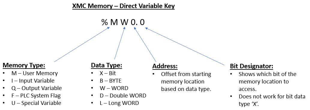
The M memory area is defined through direct variables by data type. For Modbus TCP communications, a direct memory address tag is required for data transfer. If using tags in the same memory area with a different data type designator, ensure that each tag is referencing a unique memory address, or data could be written over.
| Data Type Designation | Designated Range of Variable Address |
|---|---|
| X (bit) – 1 bit | %MX0 ~ %MX16777215 |
| B (byte) – 8 bits | %MB0 ~ %MB2097151 |
| W (word) – 16 bits | %MW0 ~ %MW1048575 |
| D (double word) – 32 bits | %MD0 ~ %MD524287 |
| L (long word) – 64 bits | %ML0 ~ %ML262143 |
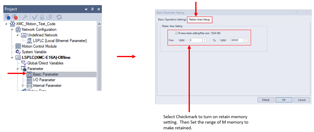
The M Memory area can be configured to retain a portion of the memory range. This will keep data of the configured memory range when the XMC is power cycled.
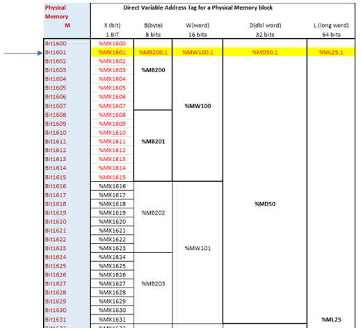
Memory can be defined by different direct variable name based on the Data Type designation (X, B, W, D, L). A physical memory location will overlap with the other data type designations in the M Memory area. For example , we will pick the memory BIT location designated by %MX1601. %MX1601 can also be defined as:
-
%MB200.1
-
%MW100.1
-
%MD50.1
-
%ML25.1
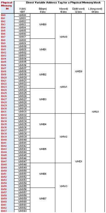
The %M direct variable memory area has shared memory across different data types. This can be used to have the XMC automatically convert BYTE arrays into WORD or DWORD arrays.
-
The BYTE array size must be divisible by 2 with no remainder to provide a valid WORD array size.
-
The BYTE array size must be divisible by 4 with no remainder to provide a valid DWORD array size.
-
A WORD array can also be converted to BYTE, DWORD or LWORD data array.
-
A DWORD array can be converted to BYTE, WORD, or LWORD data array.
The chart below shows %ML0 data contains %MD0 and %MD1 data.
-
%MD0 data contains %MW0 and %MW1 data.
-
%MW0 data contains %MB0 and %MB1 data.
-
%MB0 data contains %MX0 thru %MX7 data.
%M Memory Variable Declaration Example
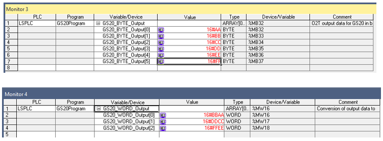
In this example, we are using an array of 32 bytes as an input and 6 bytes as an output to a GS20 VFD. The input arrays can use BYTE, WORD, and DWORD because the original size of 32 is evenly divisible by 2 and 4. The output arrays can only use BYTE and WORD since the original size of 6 is only evenly divisible by 2. The Address Calculator can be used to determine proper memory addresses when converting between data types.

Data Conversion Monitoring
Connecting to the XMC and starting Monitor Mode will allow us to look at the data being converted to the different data types. The images of the input data conversion show the automatic conversion from BYTE data to WORD and DWORD for the Input Data. The images of the output data conversion shows automatic conversion from BYTE data to WORD data.
Input Data Conversion:
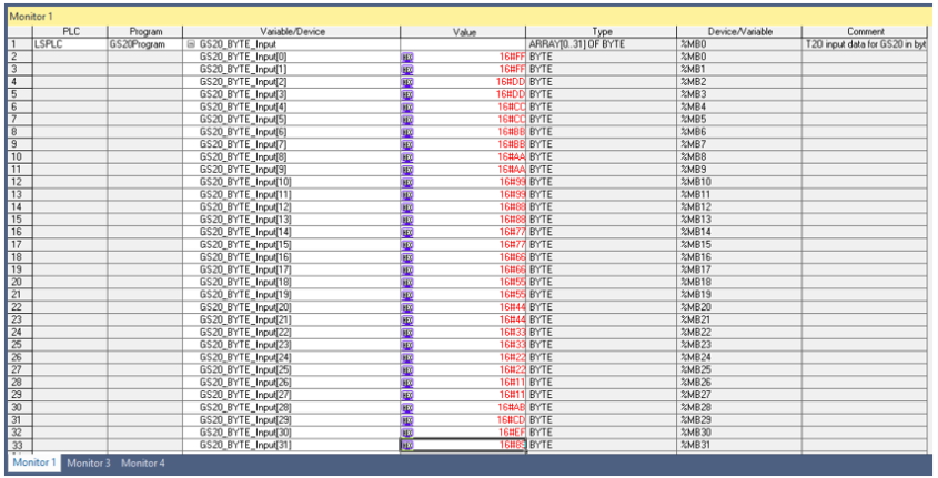

Output Data Conversion:
Note: DWORD is not done since the original output byte array size of 6 is not evenly divisible by 4.
The Address Calculator can be used to determine proper memory addresses when converting between data types. It is in the XG5000 Tools menu.


LM101