XMC Motion Controller Hardware Overview
Expand the topics below for details about available XMC models, specifications, and power connections.
| Model Number | Power Supply | # of EtherCAT Axes |
# of EtherCAT Nodes |
Inputs | Outputs | Analog Inputs | Analog Outputs | Encoder Inputs |
|---|---|---|---|---|---|---|---|---|
| XMC-E08A | 100 to 240 VAC | 8 | 16 | 8 | 16 | 2 channels | 2 channels | 2 channels |
| XMC-E08A/DC | 19.2 to 28.8 VDC | 8 | 16 | 8 | 16 | |||
| XMC-E16A | 100 to 240 VAC | 16 | 32 | 8 | 16 | |||
| XMC-E16A/DC | 19.2 to 28.8 VDC | 16 | 32 | 8 | 16 |
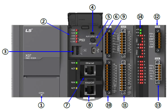
| Number | Name | Content |
|---|---|---|
| 1 | Power input | 110/220 VAC power input and 24VDC output, or 24VDC input for DC systems. |
| 2 | Status display |
Displays the motion controller's operation mode:
See CPU Status Indicators below for details. |
| 3 | SD card connector | SD memory card slot. |
| 4 | Mode switch |
Sets the motion controller's operation mode.
See CPU Mode Switch below for details. |
| 5 | SD card command button |
Three operations possible:
|
| 6 | USB mini-B connector | USB connection access for XG5000. |
| 7 | Ethernet connector | Port to communicate Ethernet and connection access for XG5000. |
| 8 | EtherCAT port | EtherCAT port for controlling EtherCAT nodes. |
| 9 | Encoder input connector | Encoder input signals. |
| 10 | Digital input connector | Connector that accepts digital input signal. |
| 11 | Digital output connector | A connector that outputs a digital output signal. |
| 12 | Analog input connector | Connector that accepts analog input signal. |
| 13 | Analog output connector | A connector that outputs analog output signal. |
| 14 | Input/output display | Digital input/output, analog input/output, encoder input LED status. |
CPU Status Indicators
| Indicator Label | Description |
|---|---|
| PWR | Red LED is illuminated when power is on. |
| RUN | Green LED is illuminated when CPU is in RUN mode. |
| ERR | Red LED is illuminated to indicate an error. OFF if no error is present. |
| STATE | Red light ON when the SD card is installed. The red light flickers when an SD card error occurs. |
| RD/WR | Flickering Red during SD memory reads or writes. |
CPU Mode Switch
| Switch Label | Description |
|---|---|
| RUN | Executes the user program. Online edits are possible. Cannot perform a full Write from XG5000 when the switch is in this position. |
| STOP | Default behavior is to not RUN the program. This is the default position of the CPU. XG5000 allows the user to use this position as a Remote Run from their program. XG5000 can perform a full Write operation when the switch is in this position. |
| RST | Reset the program's operational state. |
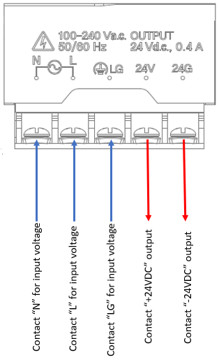
The diagram below applies to XMC-E08A and XMC-E16A models.
-
100-240 VAC single-phase input.
-
Built-in 24VDC output that can supply 0.4 amps.
-
See the XMC User Manual (section 3.3.4) for grounding information.
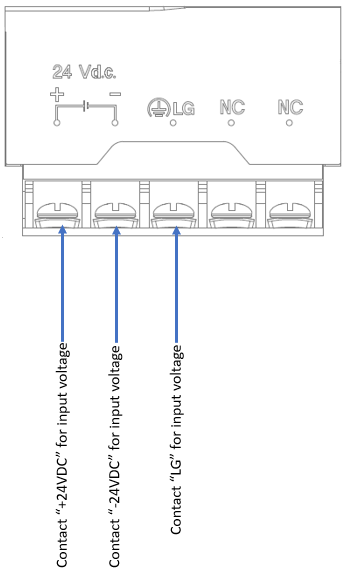
The diagram below applies to XMC-E08A/DC and XMC-E16A/DC.
-
DC input rating is 19.2-28.8 VDC.
-
See the XMC User Manual (section 3.3.4) for grounding information.

LM000