XGB EtherCAT Helical Interpolation
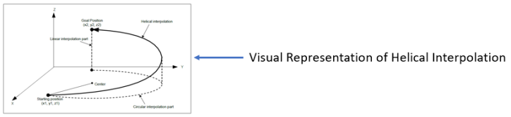
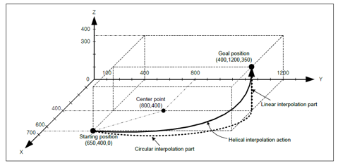
Helical interpolation is used to move two axes in a circular path based on the target position and type of circular interpolation mode and a third axis is executing a linear interpolation synchronizing with the circular interpolation.
-
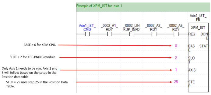
The XPM_IST function block is used to execute the helical interpolation from the Position data table.
-
The axes being controlled must already be configured using the XG-PM software before using XPM_IST.
-
XPM_ECON and XPM_SVON must be executed before any helical interpolation moves.
-
This example is in scan program LP633_HelicalInterpolation_Example in OnlineHelp_ECAT_Example.
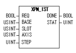
| Element Name | Element Type | Description |
|---|---|---|
| REQ | Input | Edge detected request to execute the function block. |
| BASE | Input | Base number of the motion controller. Set to 0. |
| SLOT | Input | Slot number of the motion controller. Set to the slot number of the XBF-PN04B or XBF-PN08B module. |
| AXIS | Input | Axis number of the main axis for the helical interpolation move. XBF-PN04B:1~4, XBF-PN08B:1~8 |
| STEP | Input | Step to execute in the position table. Must be a value between 0 – 400. If value is set to 0, then the current step is executed. This can be a constant or variable. |
| DONE | Output | Status that function block is done. |
| STAT | Output | Current status of the function block. Non-zero numbers will be an error or warning. |
The position table is setup in the XG-PM software.
| Step | Action |
|---|---|
| 1 |
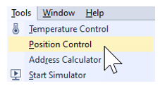
Open the XG5000 project for the application. Go to Tools menu èPosition Control to open XG-PM software.
|
| 2 |
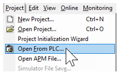
Open the XG-PM project or Connect to PLC and select ProjectèOpen from PLC.
|
| 3 |
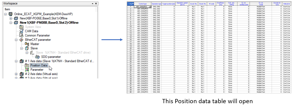
Open the Position data table in the Workspace for the axis that is being configured. This example shows Axis #1.
|
-
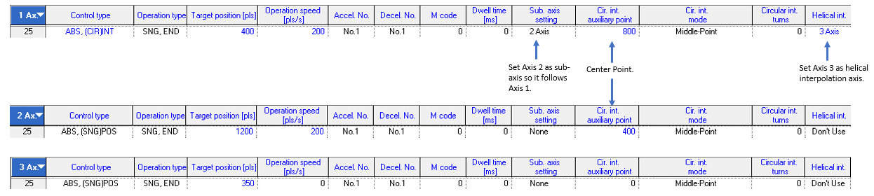
Axis 1 is the main axis. Set cir. Int. mode to Middle-Point. Set the target position for the X component of the movement.
-
Axis 2 is the sub axis. Set cir. Int. mode to Middle-Point. Set the target position for the Y component of the movement.
-
Axis 3 is the helical interpolation axis for the main Axis 1. Set target position for the Z component of the movement.
-
The circular interpolation mode can be set to Middle-Point, Center-Point, CW or Center-Point, CCW.
-
A valid circular interpolation auxiliary point (center point) must be entered for Axes 1 and 2.
-
Axis 1 control type is set to ABS, (CIR)INT. Axis 2 & 3 can be left at the default value.
-
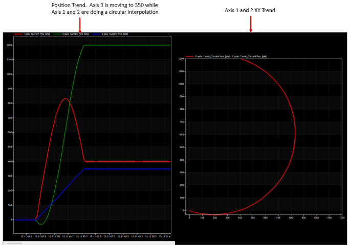
In this example the starting points for Axis 1, 2 and 3 are (0,0,0). The center point of the circle is chosen to be (800,400)
-
The target positions for Axis 1, 2 and 3 are (400,1200,700).
-
Step 25 in the Position table is being used for the helical interpolation move.
XPM_IST Code for Example
XG-PM Trend of Example
LP633