XGB EtherCAT Reading Axis Operation and State Data
The XPM_CRD function block is used to read operation information such as current position, speed and torque. The XPM_SRD function block is used to read the current state of an axis. XPM_ECON needs to be executed first so EtherCAT servo drives are connected to receive commands.
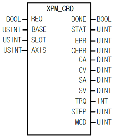
The XPM_CRD reads operation information from the axis.
| Element Name | Element Type | Description |
|---|---|---|
| REQ | Input | Enable the function block. Data will be constantly updated with REQ = TRUE. |
| BASE | Input | Base number of the motion controller. Set 0 to the Base Number. |
| SLOT | Input | Slot number of the motion controller. Set to the slot number of the XBF-PN04B or XBF-PN08B module. |
| AXIS | Input | Axis to command with function block. XBF-PN04B:1~4, XBF-PN08B:1~8 |
| DONE | Output | Status that function block is done. |
| STAT | Output | Current status of the function block. Non-zero numbers will be an error or warning. |
| ERR | Output | Displays axis error number. |
| CERR | Output | Displays common error number. |
| CA | Output | Axis commanded position. |
| CV | Output | Axis commanded speed. |
| SA | Output | Axis current position. |
| SV | Output | Axis current speed. |
| TRQ | Output | Axis current torque. |
| STEP | Output | Display step number of the current operation from the position data table. |
| MCD | Output | Display M code value. |
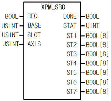
The XPM_SRD reads axis state information.
| Element Name | Element Type | Description |
|---|---|---|
| REQ | Input | Enable the function block. Data will be constantly updated with REQ = TRUE. |
| BASE | Input | Base number of the motion controller. Set 0 to the Base Number. |
| SLOT | Input | Slot number of the motion controller. Set to the slot number of the XBF-PN04B or XBF-PN08B module. |
| AXIS | Input | Axis to command with function block. XBF-PN04B:1~4, XBF-PN08B:1~8 |
| DONE | Output | Status that function block is done. |
| STAT | Output | Current status of the function block. Non-zero numbers will be an error or warning. |
| ST1 | Output | Boolean array of state information. See XPM_SRD State Details for more details. |
| ST2 | Output | |
| ST3 | Output | |
| ST4 | Output | |
| ST5 | Output | |
| ST6 | Output | |
| ST7 | Output |
ST1:
| Element Number | Description |
|---|---|
| 0 | Operating Status. 0 = Stop, 1 = Busy |
| 1 | 0 = No Error, 1 = Error State |
| 2 | Positioning complete status |
| 3 | M code On signal 0 = off, 1 = on |
| 4 | Homed status 0 = not homed yet, 1 = home completed |
| 5 | 0 = no common error, 1 = common error present |
| 6 | Stop status state |
| 7 | Reading/Writing variable data is active |
ST2:
| Element Number | Description |
|---|---|
| 0 | Upper Limit Detection |
| 1 | Lower Limit Detection |
| 2 | Emergency Stop status |
| 3 | Movement Direction. 0 = forward, 1 = reverse |
| 4 | In acceleration |
| 5 | In constant speed |
| 6 | In deceleration |
| 7 | In dwell |
ST3:
| Element Number | Description |
|---|---|
| 0 | Axis in positioning control state |
| 1 | Axis in speed control state |
| 2 | Axis in linear interpolation state |
| 3 | Not used |
| 4 | Axis in circular interpolation state |
| 5 | Axis in homing operation |
| 6 | Axis in synchronous position start operation |
| 7 | Axis in synchronous speed start operation |
ST4:
| Element Number | Description |
|---|---|
| 0 | Axis in jog operation |
| 1 | Not used |
| 2 | Axis in inching operation |
| 3 | Not used |
| 4 | Axis returning to position before manual operation |
| 5 | Axis in CAM control operation |
| 6 | Axis in Feed control operation |
| 7 | Axis in ellipse interpolation operation |
ST5:
| Element Number | Description |
|---|---|
| 0 | Axis number: XBF-PN04B:1~4, XBF-PN08B:1~8, 9: Encoder1 |
| 1 | |
| 2 | |
| 3 | |
| 4 | 0 = Main Axis, 1 = Sub axis |
| 5 | Not used |
| 6 | Not used |
| 7 | 0 = no read/write parameter active, 1 = processing servo read/write parameter |
ST6:
| Element Number | Description |
|---|---|
| 0 | Emergency Stop or Deceleration stop signal |
| 1 | Not used |
| 2 | Not used |
| 3 | Not used |
| 4 | Upper limit signal |
| 5 | Lower limit signal |
| 6 | Home signal |
| 7 | DOG signal |
ST7:
| Element Number | Description |
|---|---|
| 0 | External command signal |
| 1 | Servo on signal |
| 2 | Servo alarm signal |
| 3 | In position signal |
| 4 | In position signal |
| 5 | Declination counter clear output signal |
| 6 | Not used |
| 7 | 0 = communication normal, 1 = communication error |
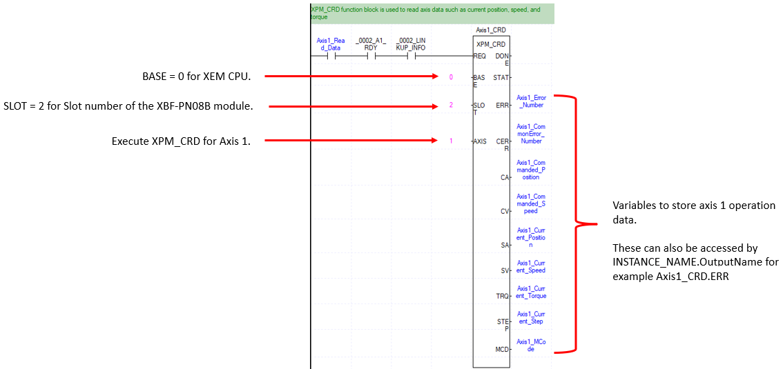
The following examples can be found in OnlineHelp_ECAT_Example in the LP622_Read_Data_Example Scan program.
This example shows using the XPM_CRD function block to read operation data for Axis 1. XPM_ECON must be executed successfully before enabling XPM_CRD.
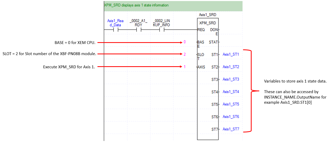
This example shows using the XPM_SRD function block to read state data for Axis 1. XPM_ECON must be executed successfully before enabling XPM_CRD.
LP622