XG5000 and XG-PM Project Creation with EtherCAT Modules
Video Tutorial
The XEM CPU is capable of controlling EtherCAT Servo drives using the XBF-PN04B or XBF-PN08B modules.
-
The XEM CPU can have two of these modules connected to provide 2 EtherCAT servo networks.
-
These modules must be in Slot 2 if only using one module or Slots 2 and 3 if using two modules.
-
The XBF-PN04B and XBF-PN08B only control EtherCAT servo drives and remote I/O is not supported.
-
XG5000 and XG-PM are used in configuring and controlling EtherCAT servo drives with the XEM CPU.
-
XG5000 is used to create a program to control the servo drives.
-
XG-PM is used to setup drive parameters and create any CAM data.
-
This example program is available in OnlineHelp_ECAT_Example.
| Step | Action |
|---|---|
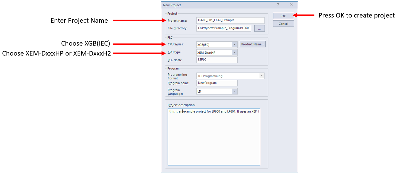
| 1 |
Open XG5000 and create a new project. Fill out project information and Press OK to complete creation.
|
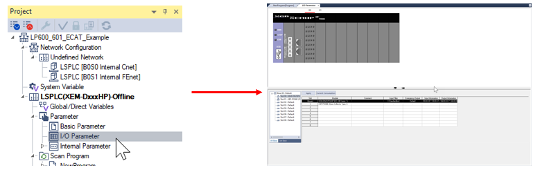
| 2 |
Open I/O Parameter screen from the Project window.
|
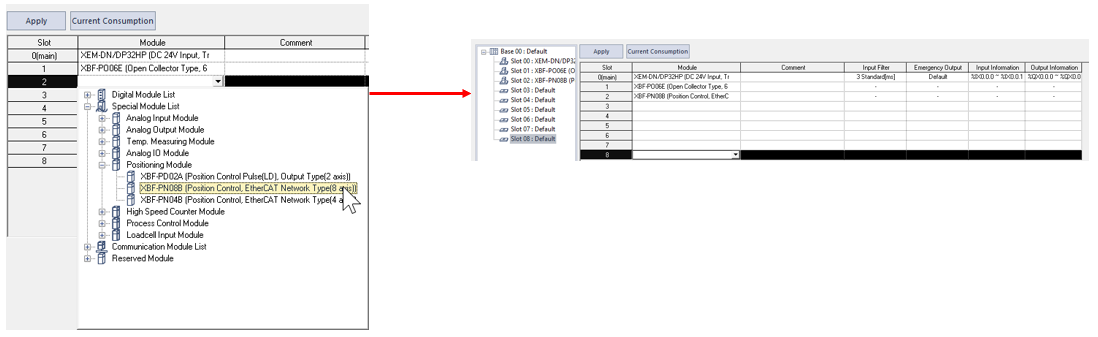
| 3 |
Add the XBF-PN04B or XBF-PN08B to Slot 2. These modules must be in Slot 2 when only one module is used or Slots 2 and 3 if two modules are being used. No more than two EtherCAT modules can be installed. This example shows XBF-PN08B.
|
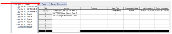
| 4 |
Press the Apply button to create the global variables for the XBF-PN08B or XBF-PN04B module(s).
|
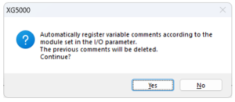
| 5 |
Press Yes to register the global variables for the module(s).
|
| 6 |
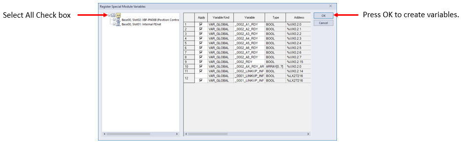
Select all the variables for creation. Press OK to create them.
|
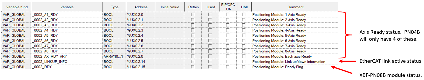
This example shows the special module variables for XBF-PN08B.
This example requires a connection to the XGB PLC Rack containing an XBF-PN04B or XBF-PN08B module.
-
ADC recommends configuring drive node numbers to match the desired axis number.
-
XBF-PN04B supports node numbers 1 ~ 4 for servo drives.
-
XBF-PN08B supports node numbers 1 ~ 8 for servo drives.
| Step | Action |
|---|---|
| 1 |
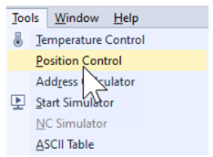
Open XG-PM software from XG5000. Go to Tools menu è Position Control.
|
| 2 |
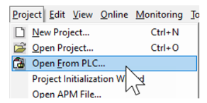
From XG-PM, select Project menuè Open From PLC…
|
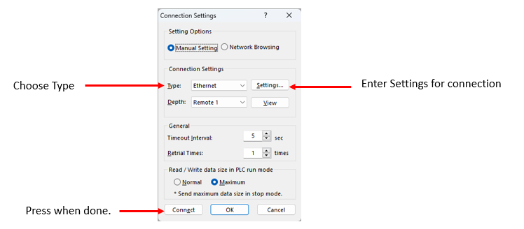
| 3 |
Enter the Connection Settings. This example is using Ethernet. Press Connect when done.
|
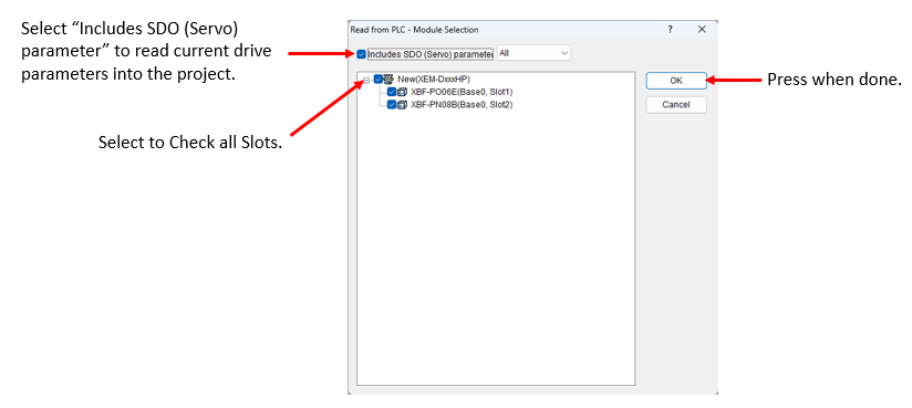
| 4 |
Select all available slots. This will add the built-in PTO and EtherCAT module(s) to the project. Select the Includes SDO (Servo) parameter check box. Note: Drive node numbers must be set to Axis number before opening from PLC. This will make the drive node number match the project's axis number when selecting Includes SDO (Servo) parameter.
|
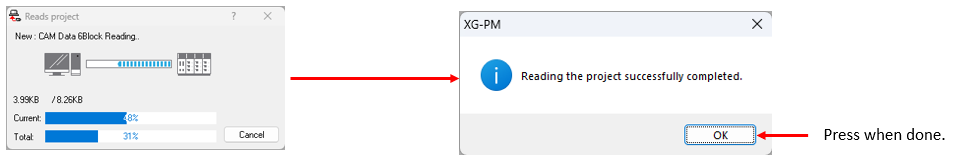
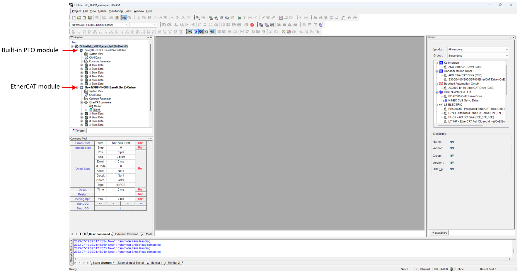
| 5 |
Status screen will show project being read from XEM CPU. Press OK on success pop up screen.
|
| 6 |
Save project and proceed to XG-PM EtherCAT Axis Configuration.
|
LP601