CAM Data Creation and Using XPM_CAM or XPM_CAMO
XEM CPU supports up to 8 different CAM blocks using various CAM profiles.
-
The CAM blocks are created in XG-PM software.
-
The XPM_CAM and XPM_CAMO function blocks are used to execute any created CAM blocks.
-
A User CAM operation is available and is accessed as CAM block number 9.
-
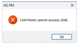
A maximum of 2048 points can be generated per CAM block. An error will appear if a block will have too many points.
-
A CAM block supports one master axis and one sub-axis.
| Function Block | Description in XG5000 | Function |
|---|---|---|
| XPM_CAM | CAM run | Execute a predefined CAM block with the slave axis according to the movement of the master axis. |
| XPM_CAMO | CAM run with master offset | Execute a predefined CAM block with the slave axis after the master axis moved the distance defined as the offset. |
These examples show control of Axis 1 by an XEM-DN32HP CPU.
-
Axis 1 is a LS Electric L7CA004U-AD connected to a linear actuator with a 5 mm pitch.
-
The L7C servo drive is configured to have 1000 pulses be one revolution of the motor.
| Step | Action |
|---|---|
| 1 |
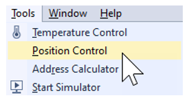
Open the XG5000 project for the application. Go to Tools menu èPosition Control to open XG-PM software.
|
| 2 |
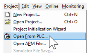
Open the XG-PM project or connect to PLC and select ProjectèOpen from PLC.
|
| 3 |
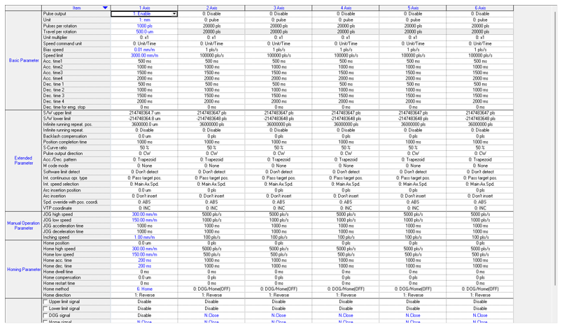
Open the Parameter file in the Workspace for the axis that is being configured. This example shows Axis #1.
This parameter screen will open:
|
| 4 |
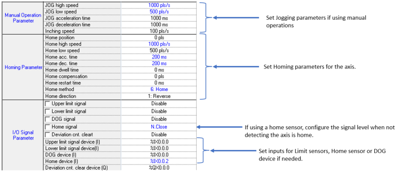
Configure the parameters of the Axis. This example shows Axis 1.
|
| 5 |
Save the project. Connect to the CPU and write the project to the CPU. Note: If connecting XG5000 and XG-PM at the same time, make sure to connect XG5000 first. XG5000 will give error messages if it is connected last. |
The XG-PM software is used to create CAM blocks 1 - 8.
| Step | Action |
|---|---|
| 1 |
Open the XG5000 project for the application. Go to Tools menu è Position Control to open XG-PM software.
|
| 2 |
Open the XG-PM project or connect to PLC and select Project è Open from PLC.
|
| 3 |
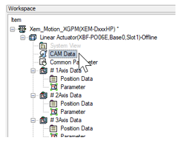
Open the CAM Data file in the Workspace.
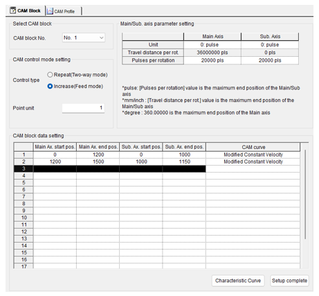
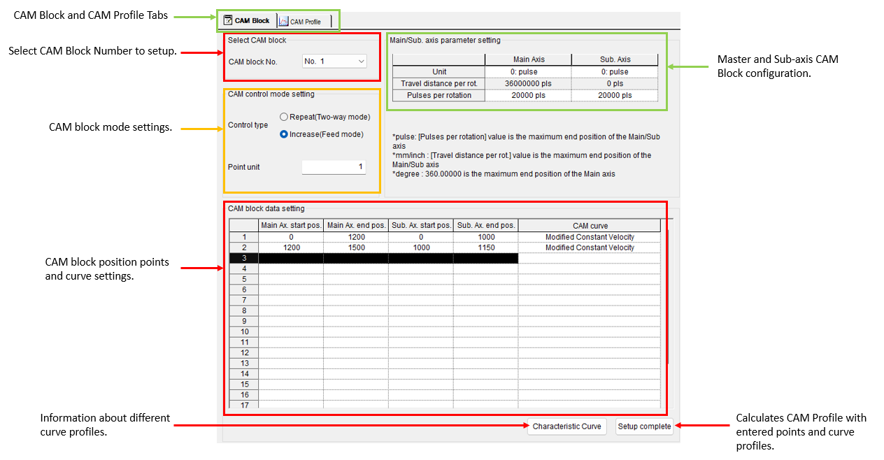
The CAM Block screen will open:
|
| Step | Action |
|---|---|
| 1 |
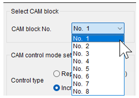
Choose a CAM block number to configure.
|
| 2 |
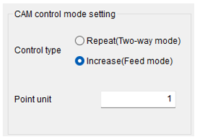
Configure the CAM block mode settings.
|
| 3 |
Configure Main and Sub axis parameters.
|
| 4 |
Enter CAM block data. Make sure block data matches restrictions of CAM block configuration.
|
| 5 |
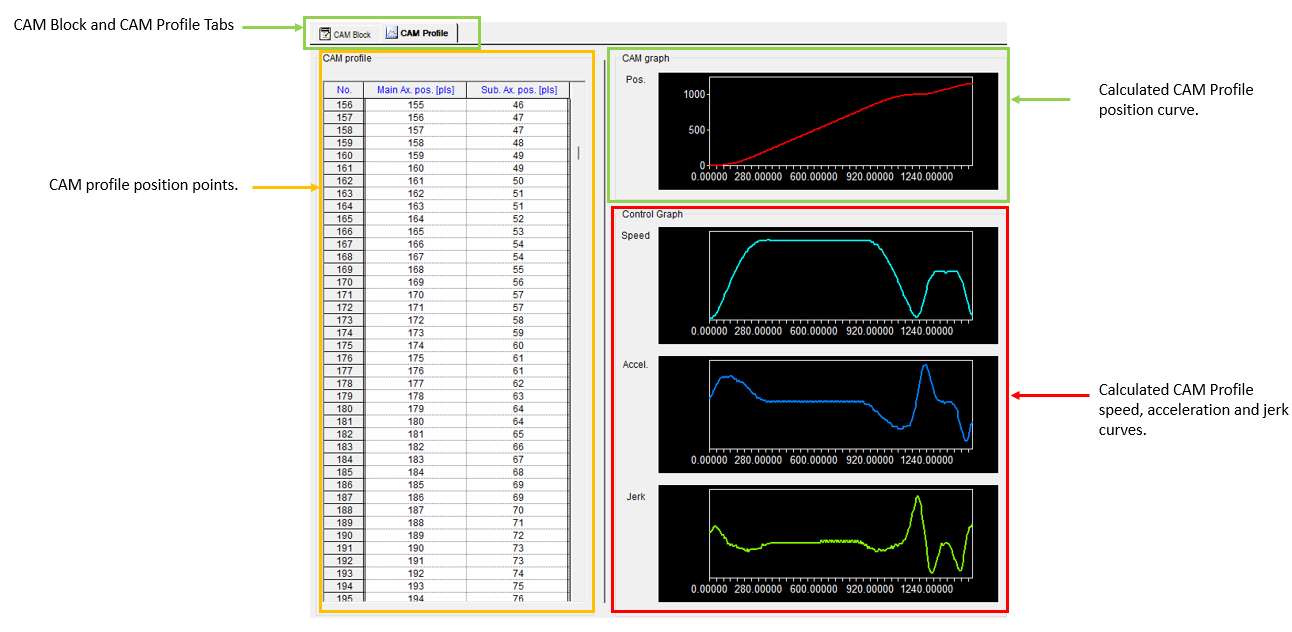
Press Setup complete button to calculate the CAM Profile.
Goes to CAM Profile screen when successful.
Error message if there is a problem
|
| 6 |
Save the project. Connect to the CPU and write the project to the CPU. Note: If connecting XG5000 and XG-PM at the same time, make sure to connect XG5000 first. XG5000 will give error messages if it is connected last. |
Using XPM_CAM and XPM_CAMO
See the topics below for examples using XPM_CAM and XPM_CAMO.
LP533


