High Speed Counter Setup - CPU Based
This help topic covers the basics of the CPU built-in high speed counter feature and walks through an example to configure this feature and how to program to use this feature.
All of the XEM CPU modules support the same high speed counter feature. Here is the summary of their specifications.
| Feature | XEM-DN/DP32H2 and XEM-DN/DP32HP |
|---|---|
| Number of counter inputs | 4 (Channel 0-3) |
| Counter Mode | Linear or Ring |
| Pulse Input Mode | 1 Phase 1 input, 1 Phase 2 inputs, CW/CCW or 2 Phases (x4) |
| Maximum Count Speed | 200kpps (1 phase) or 100kpps (2 phases) |
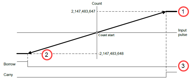
| Count Range | -2,147,483,648 to 2,147,482,647 (DINT) |
| Compare Mode | 2 compare modes per channel |
| Presets | Internal and External |
XG5000 has a window that makes the high speed counter configuration easier.
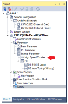
Double-click High Speed Counter in the Project window.
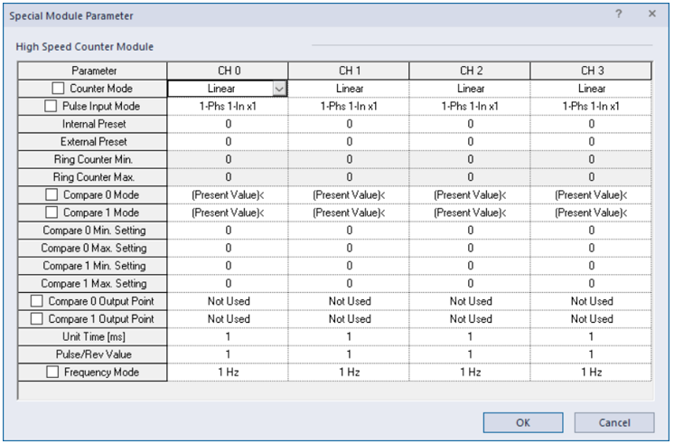
The Special Module Parameter window opens.
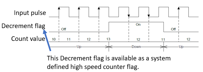
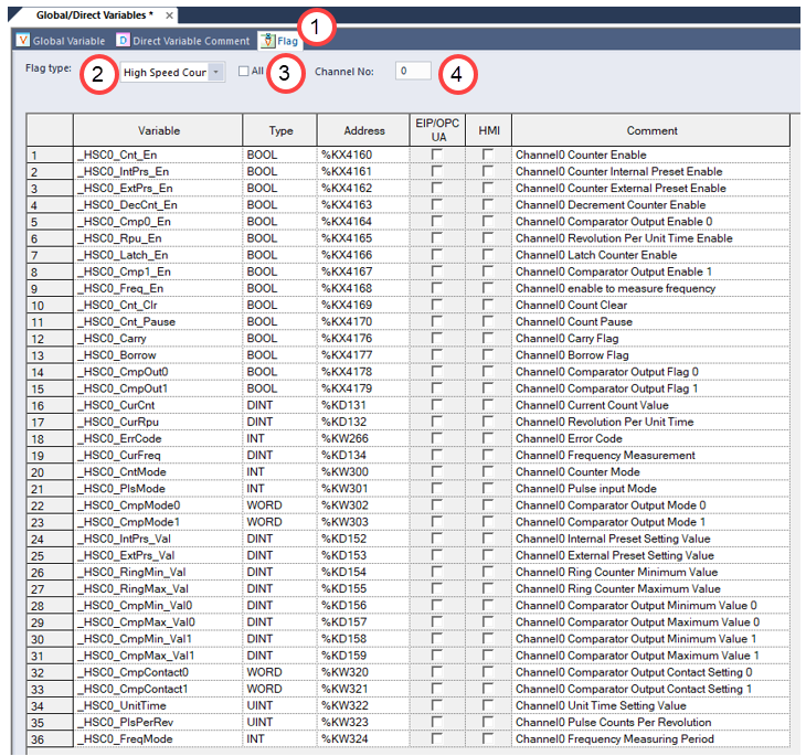
The XEM CPU modules support 36 predefined flags for each channel. You can use these flags for programming and monitoring.
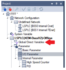
Double-click Global/Direct Variables in the Project window.
| Step | Action |
|---|---|
| 1 | Select the Flag tab. |
| 2 | Select High Speed Counter. |
| 3 |
Uncheck All. |
| 4 | Enter the channel number (0-3). |
There are 2 counter modes available.
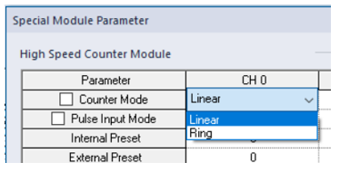
There are 4 pulse input modes available.
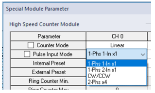
Each high speed counter channel has two sets of Compare Modes that are named Compare 0 Mode and Compare 1 Mode.
Each Compare Mode supports seven conditions to evaluate the Present Value (Current count value) with up to two compare setup values (Minimum and Maximum Setting) and controls the Comparator Output flag. A digital output built in the CPU module can also be controlled (this is optional).
Note: The Comparator Output flag is a predefined high speed counter flag.
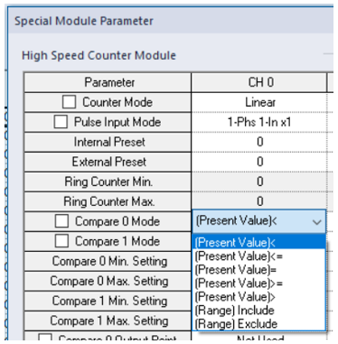
| Condition | Minimum Setting | Maximum Setting | Comparator Output Flag | Digital Output (Optional) |
|---|---|---|---|---|
| (Present Value)< | Required | Not required | On if Present Value < Minimum Value. | On if the Comparator flag is on. |
| (Present Value)<= | Required | Not required | On if Present Value <= Minimum Value. | On if the Comparator flag is on. |
| (Present Value)= | Required | Not required | On if Present Value = Minimum Value. | On if the Comparator flag is on. |
| (Present Value)>= | Required | Not required | On if Present Value >= Minimum Value. | On if the Comparator flag is on. |
| (Present Value)> | Required | Not required | On if Present Value > Minimum Value. | On if the Comparator flag is on. |
| (Range) Include | Required | Required | On if Present Value >= Minimum Value and Present Value <= Maximum Value. | On if the Comparator flag is on. |
| (Range) Exclude | Required | Required | On if Present Value <= Minimum Value or Present Value >= Maximum Value. | On if the Comparator flag is on. |
There are 2 types of presets available.
Internal Preset
When the Internal Preset Enable flag is turned on, the value stored in the Internal Preset Setting Value variable is set as the count value for the channel.
| Item | CH 0 | CH 1 | CH 2 | CH 3 |
|---|---|---|---|---|
| Internal Preset Enable |
_HSC0_IntPrs_En
|
_HSC1_IntPrs_En
(%KX4321) |
_HSC2_IntPrs_En
(%KX4481) |
_HSC3_IntPrs_En
(%KX4641) |
| Internal Preset Setting Value | _HSC0_IntPrs_Val
(%KD152) |
_HSC1_IntPrs_Val
(%KD167) |
_HSC2_IntPrs_Val
(%KD182) |
_HSC3_IntPrs_Val0 (%KD197) |
External Preset
To use this External Preset, turn on the External Preset Enable flag assigned to the channel first. After that, when the External Preset Command turns on, the value stored in the External Preset Setting Value variable is set to the channel as the count value.
| Item | CH 0 | CH 1 | CH 2 | CH 3 |
|---|---|---|---|---|
| External Preset Enable | _HSC0_ExtPrs_En
(%KX4162) |
_HSC1_ExtPrs_En
(%KX4322) |
_HSC2_ExtPrs_En
(%KX4482) |
_HSC3_ExtPrs_En
(%KX4642) |
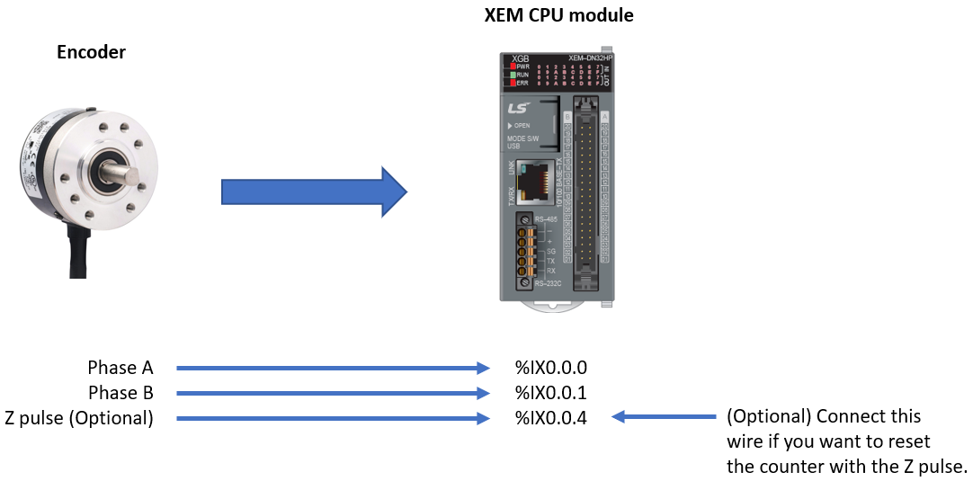
| External Preset Command | %IX0.0.4 | %IX0.0.5 | %IX0.0.6 | %IX0.0.7 |
| External Preset Setting Value | _HSC0_ExtPrs_Val
(%KD153) |
_HSC1_ExtPrs_Val
(%KD168) |
_HSC2_ExtPrs_Val
(%KD183) |
_HSC3_ExtPrs_Val
(%KD198) |
%IX0.0.0 - %IX0.0.7 can be assigned to the high speed counter feature on all XEM CPU modules.
| Channel | Pulse Input | External Preset Command Input |
|---|---|---|
| CH 0 | %IX0.0.0 | %IX0.0.4 |
| CH 1 | %IX0.0.1 | %IX0.0.5 |
| CH 2 | %IX0.0.2 | %IX0.0.6 |
| CH 3 | %IX0.0.3 | %IX0.0.7 |
Important!
When a pulse input mode uses 2 pulse inputs, the mode must use CH 0&CH 1 or CH 2&CH 3 for the pulse inputs. Other combinations are not allowed.
| Pulse Input Mode | Number of Pulse Inputs to Use | Available Channels |
|---|---|---|
| 1 Phase 1 input | 1 | CH0, CH1, CH2 or CH3 |
| 1 Phase 2 inputs | 2 | CH 0 & CH 1 or CH 2 & CH 3 |
| CW/CCW | 3 | CH 0 & CH 1 or CH 2 & CH 3 |
| 2 Phases (x4) | 4 | CH 0 & CH 1 or CH 2 & CH 3 |
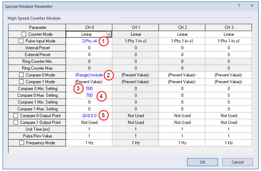
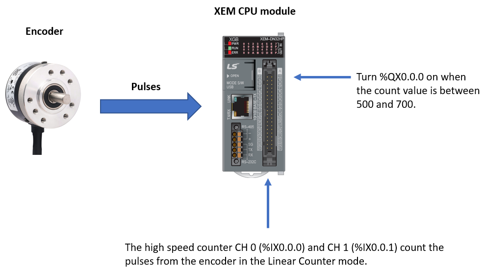
Count pulses from an encoder and turn %QX0.0.0 on when the count value is between 500 and 700.
System Configuration
| Step | Action |
|---|---|
| 1 |
Configure the high speed counter channel 0 (CH 0) and channel 1 (CH 1) like follows.
|
| 2 |
Connect the encoder to the XEM CPU module.
Also connect 24V and 0V correctly according to the CPU module type. |
| 3 |
Write a program. LD (Ladder)
ST (Structured Text)
|
| 4 |
Results: Current Count Value = 365
Current Count Value = 570
Current Count Value = 712
|
LP524
