Linear Interpolation
Linear interpolation is used to move two axes in a linear path based on the target position of both the main and sub axes.
-
The XEM-DxxxHP CPUs can support up to 6 axes in linear interpolation.
-
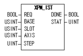
The XPM_IST function block is used to execute the linear interpolation from the Position data table.
-
The axes being controlled must already be configured using the XG-PM software before using XPM_IST.
Video Tutorial
XPM_IST Details
| Element Name | Element Type | Description |
|---|---|---|
| REQ | Input | Edge detected request to execute the function block |
| BASE | Input | Base number of the motion controller.Equal to 0 for built-in position control. |
| SLOT | Input | Slot number of the motion controller.Equal to 1 for built-in position control |
| AXIS | Input | Axis number of the main axis for the linear interpolation move.Set to 1 thru 6 for built-in axes. This can be a constant or variable. |
| STEP | Input | Step to execute in the position table.Must be a value between 0 – 400.If value is set to 0, then the current step is executed.This can be a constant or variable. |
| DONE | Output | Status that function block is done. |
| STAT | Output | Current status of the function block.Non-zero numbers will be an error or warning. |
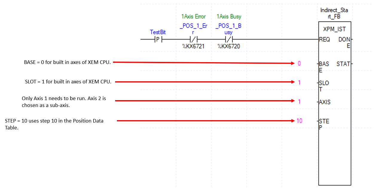
This example shows control of Axis 1 and 2 by an XEM-DN32HP CPU.
-
Axis 1 is the main axis and Axis 2 is the sub axis.
-
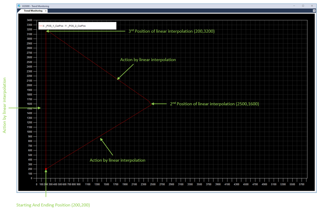
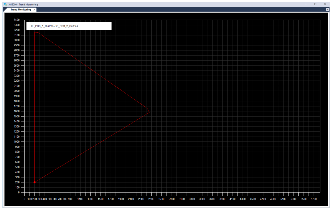
The example will perform 3 linear interpolation steps to create a triangle.
-
See Visual Representation of Linear Interpolation Triangle for a visual representation of the 3 linear interpolation moves.
| Step | Action |
|---|---|
| 1 |
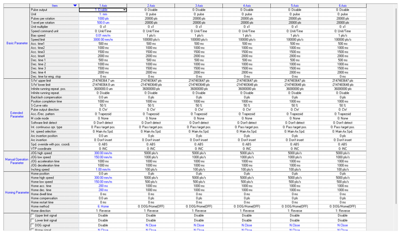
Open the XG5000 project for the application. Go to Tools menu è Position Control to open XG-PM software.
|
| 2 |
Open the XG-PM project or connect to PLC and select Projectè Open from PLC.
|
| 3 |
Open the Parameter file in the Workspace for the axis that is being configured. This example shows Axis #1.
This parameter screen will open:
|
| 4 |
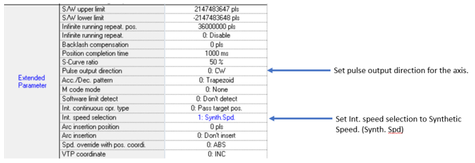
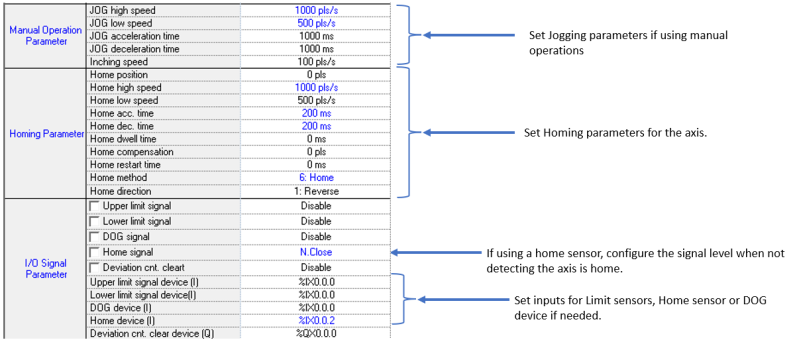
Configure the parameters of the Axis. This example shows Axis 1.
|
| 5 | Configure Axis 2. |
| 6 |
Save the project. Connect to the CPU and write the project to the CPU. Note: If connecting XG5000 and XG-PM at the same time, make sure to connect XG5000 first. XG5000 will give error messages if it is connected last. |
The Position table is setup in the XG-PM software.
| Step | Action |
|---|---|
| 1 |
Open the XG5000 project for the application. Go to Tools menu è Position Control to open XG-PM software.
|
| 2 |
Open the XG-PM project or connect to PLC and select Projectè Open from PLC.
|
| 3 |
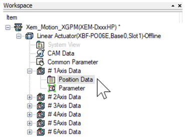
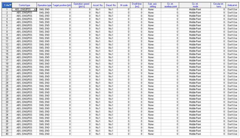
Open the Position Data table in the Workspace for the axis that is being configured. This example shows Axis #1.
The position data table will open:
|
The same step number needs to be used for both the main and sub axes.
-
Steps 10 thru 12 for Axis 1 and 2 will perform 3 linear interpolation moves to draw a triangle.
-
Axis 1 is the main axis and Axis 2 is the sub axis.
-
Axis 1 control type for steps 10 thru 12 is set to ABS, (LIN)INT for absolute linear interpolation.
-
Operation type for Steps 10 and 11 are set to SNG, CONT to continue to the next step after completion. This allows the interpolation moves to be executed with one call to XPM_IST.
-
Axis 2 control type can be default for this example.
-
Starting point is (200,200).
-
Axes must be homed before performing an absolute positioning move.


XPM_IST Code for Example:
XG5000 Trend of Example:
LP521


