Parameter Configuration for Homing
Open the parameter details page to view and set parameters needed for homing.
| Step | Action |
|---|---|
| 1 | Open XG-PM from the Tools menu of XG5000. |
| 2 | Read configuration from the PLC motion CPU is it is not already populated. |
| 3 |
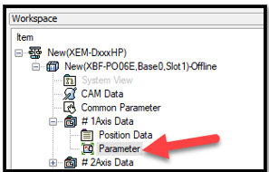
Open the axis Parameter window from the Workspace window.
|
| 4 |
Select Detail View from the Item column to see all configuration options.
|
| 5 | Refer to the sections below for parameter information and configure parameters as needed. |
-
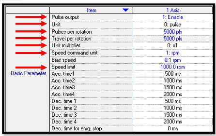
Pulse Output must be set to Enable for the PLC to be able to control the motion outputs for Axis 1.
-
Unit: One of the 4 choices, pulse, mm, inch, degree, can be designated for movement unit.
-
Pulses per rotation: Number of pulses desired for one rotation of motor.
-
Travel per rotation: Movement of the product or material for 1 rotation of motor. If a gear box is attached, gear ratio must be considered.
-
Unit multiplier: Actual Travel per rotation will be calculated by multiplying Travel per rotation and Unit multiplier.
-
Speed command unit: Unit of speed control desired
-
Speed Limit. Must match the units in Speed Command Unit.
-
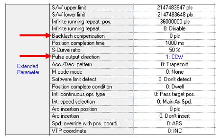
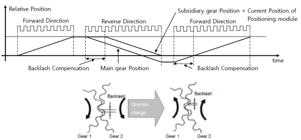
Backlash Compensation: Only needed if there is backlash present in the mechanical power transmission, e.g use of a gearbox or lead screw with possible backlash.
-
Pulse Output Direction: Direction designated will be regarded as forward direction. Refer to the servo drive or stepper drive being controlled by the PLC to determine if (CW) Clockwise or (CCW) CounterClockwise is forward.

-
JOG High/Low Speed: The speed used when manually jogging the axis. JOG high speed must be equal to or less than speed limit designated in Basic Parameter and JOG low speed must be equal to or less than JOG high speed. 0 speed cannot be designated for neither JOG high speed and low speed.
-
Inching speed: Similar to jog but one execution of Inching Operation (FB XPM_INC) will command a predefined position move. The distance travelled is defined in the XPM_INC function block in XG5000 but the speed of the incremental move is defined here in XG-PM.
-
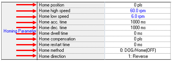
Home position: The position shown in the current position data when the homing operation is complete (EX: %KD212 for Axis 1). Changing this value will not cause the final physical home position of the machine to change, only the numerical value of the final position. The ‘Home compensation’ parameter is what can be used to physically move the axis to a different location.
-
PLC instruction XPM_PRS (Current position preset) can also change the value of the position but is not done automatically as part of the homing routine. It is a separately called instruction for setting a new value to the current position register. It is not directly related to homing setup or execution.
-
-
Home high speed: This speed is used until subordinate sensor such as DOG, origin, upper/lower limit depending on homing method is found. When homing operation is executed, the object will move with Home high speed to find sensor depending on homing method. Home high speed must be equal or less than speed limit and it must be larger than Home low speed.
-
Home low speed: While homing operation is executing, the speed will be changed to Home low speed when subordinate sensor is detected and the rest steps for homing operation will be executed. It must be less than Home high speed and larger than 0.
-
Home acc./dec. time: This parameter decides acceleration and deceleration time for homing operation.
-
Home dwell time: Dwell time is waiting time after positioning completes all deceleration pulses and correction pulses due to the servo motor settling into position. This parameter designates the dwell time used when homing operation is executed only.
-
Home compensation: If some movement is necessary after homing operation is completed, this parameter can be used. For example, homing method using DOG or origin sensor is used, homing operation will be completed at the edge of sensor. If the home position is desired to be 4 inches away from the edge of the DOG or origin sensor, then the value in this parameter will command that movement. Note: the final position reading in the ‘current position’ register will still contain the value set in the ‘Home position’ parameter above.
-
Home restart time: During the Homing sequence if the moving direction is changed by an upper or lower limit signal, the axis will stop for the time designated in Home restart time. The unit of this parameter is milliseconds. Home methods 0, 1, and 3 are the only ones that can use Home Restart Time.
-
Home direction: The initial motor rotation direction is assigned in this parameter. If wrong direction is assigned, the rotating direction will be changed when upper or lower limit sensor is detected before expected sensor is detected.
-
Home method: One of the 7 homing method can be selected for home method parameter.
-
-
-
-
-
-
-
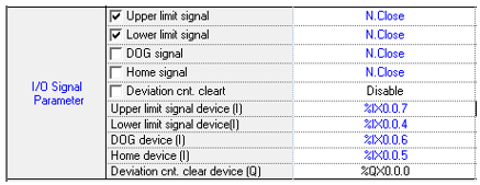
If you want to use any of these input signals then they need to be declared and set up here. Choose if you want to have the activated state to be active high (N. Open) or active low (N. Close). In general, Upper and Lower limit signals use normally closed configuration because these signals are related to personnel and machine safety function.
The signal device must be assigned N. Close or N. Open and a digital input must be assigned for the sensor to work with the homing method chosen.
If the “Deviation cnt. Clear” device is enabled, be sure to change the “Deviation cnt. Clear device (Q)” from the default of %QX0.0.0 since Axis1 uses %QX0.0.0 for Pulse Out.
The check boxes next to 5 of the parameters in the Items column allow you to alter the Normally Closed/Normally Opened/Disabled options for all axes with one change.
Example:
Upper and Lower limit boxes are checked (red arrows) and all four attributes are changed to N. Close (green arrow). Only the top to rows are changed for every axis. The bottom two rows remain unchanged for the remaining axes since the boxes were not checked.

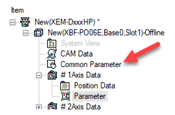
Parameters applied for all axis or encoder input built-in positioning can be assigned in Common Parameter.

-
Pulse output level: Low Active or High Active can be selected. Low Active can be regarded as negative logic and High Active can be regarded as positive logic.
After the axis configuration is complete, download to the PLC and save your file if desired. Go Offline with XG-PM and go Online with XG5000. Sometimes when both applications are connected, errors in reading or writing memory locations can be compromised.
LP514-1
