Initial Motion Configuration with Pulse Train Outputs
Video Tutorial
This topic provides an overview of using XG-PM and XG5000 to initiate motion with pulse train outputs.
-
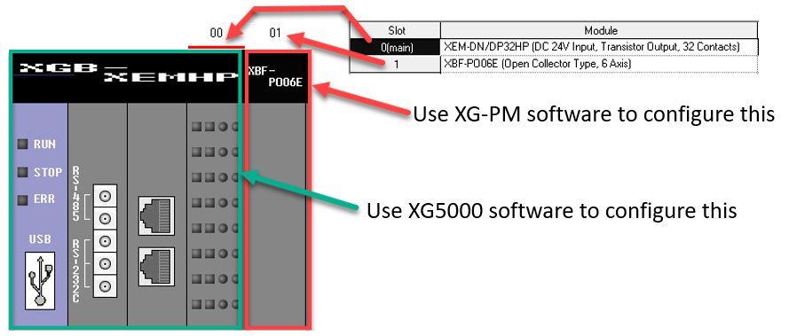
Initial Motion Configuration of a XEM CPU uses the XG-PM program.
-
XG5000 is for the main PLC project.
-
XG-PM will contain the motion specific configuration of the XEM CPU.
-
The XEM CPU has two independent processors inside running the PLC logic and Motion logic.
-
Slot 0 will be the primary CPU that runs the PLC logic and tasks.
-
Slot 1 will be the secondary CPU that handles the motion logic.
-
When connecting XG5000 and XG-PM to the XEM CPU at the same time, XG5000 must be connected first.
The XEM CPU will only allow for Pulse/Direction (Open Collector). It cannot do CW/CCW nor AB Quadrature. Here are the outputs used for Axes.
-
Axis 1 uses:
-
%QX0.0.0 for Pulse
-
%QX0.0.6 for Direction
-
-
Axis 2 uses:
-
%QX0.0.1 for Pulse
-
%QX0.0.7 for Direction
-
-
Axis 3 uses:
-
%QX0.0.2 for Pulse
-
%QX0.0.8 for Direction
-
-
Axis 4 uses:
-
%QX0.0.3 for Pulse
-
%QX0.0.9 for Direction
-
-
Axis 5 uses:
-
%QX0.0.4 for Pulse
-
%QX0.0.10 for Direction
-
-
Axis 6 uses:
-
%QX0.0.5 for Pulse
-
%QX0.0.11 for Direction
-
This section requires the user to be familiar with creating an XG5000 project and getting connected to the CPU.
Refer to Getting Connected Out of the Box for this information.
| Step | Action |
|---|---|
| 1 |
Open the XG5000 project for the XEM CPU. |
| 2 |
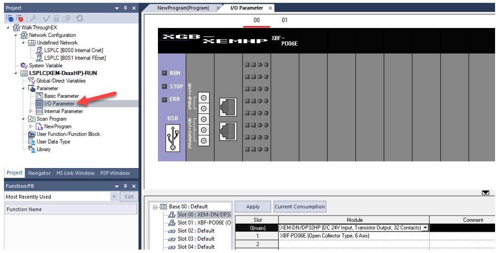
Open I/O Parameter from the Project window. This will show the XEM CPU information in Slot 0. Slot 01 will be the built-in motion CPU. This example shows the 6-axis XEM CPU.
|
| 3 |
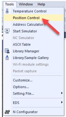
Open XG-PM to create a project for motion configuration. To Open XG-PM from XG5000, go to Tools menu è Position Control.
|
| 4 |
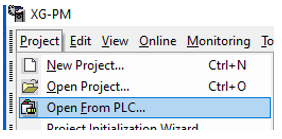
Import the motion configuration from the XEM CPU. Select Project menu è Open From PLC…
|
| 5 |
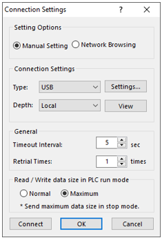
Choose the same connection settings as XG5000 for connecting to the CPU. Press Connect when done.
Note: Refer to Getting Connected Out of the Box for more information. |
| 6 |
Open the Parameter window from the Workspace window. This will open all the axes available for configuration.
|
| 7 |
Select Enable for the Pulse Output parameters for each Axis you want to use. Once an Axis has been enabled then the two pulse and direction outputs are owned for motion only. They cannot be used or manipulated in the PLC program for anything else.
Note: To ensure safe testing of the motion and to avoid machine damage or harm to personnel, ensure a proper Emergency Stop circuit has been installed. |
| 8 |
In the parameter configuration, make adjustments to the Pulses per rotation, Travel per rotation, Unit Multiplier, and Speed limit to reflect the motion system. |
| 9 |
Click Write to write the configuration to the PLC’s motion CPU.
|
| 10 |
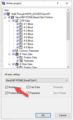
Check the Module check box to write everything to the CPU and click OK.
Note: After Step 10, XPM function blocks can be used for the enabled axes. Refer to Overview of the APM/XPM Function Blocks for the XPM function blocks. |
LP502
