Ladder Diagram Program Navigation
The Ladder Diagram is divided into rows and columns forming a grid. Each row has a label Lxxx where xxx is the row number. For instance, row zero would be L0.
The cursor will be displayed as a highlighted rectangle in a row and column. See example image below for more clarification. The cursor is used to choose where to place Ladder Diagram tools from Section 2.

Ladder Diagram code is designed to be programmed in rows and columns. Code in rows is read from left to right and code in a column is read from up to down. One ladder rung may span multiple rows and columns.


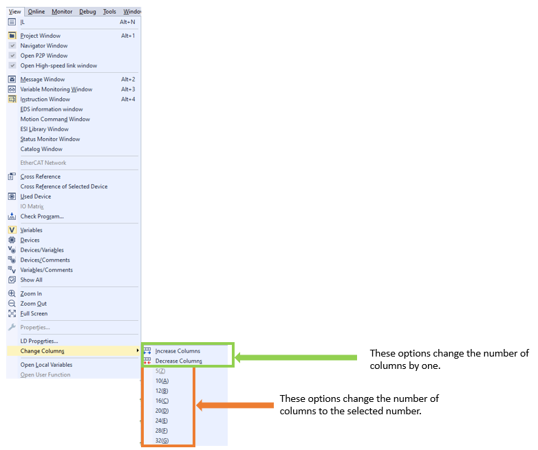
It is possible to add or subtract columns from the Ladder Editor in XG5000. This can be done from the View Menu or the View Buttons. The maximum number of Columns is 32 and the minimum is 10.


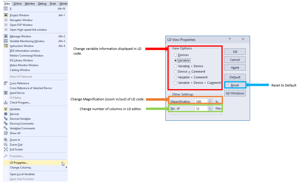
Ladder Diagram View properties can be found in the View menu è LD Properties.

LP307-3