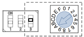
Setting L7P Node Number Switch
Set the Node ID (Modbus Address) with the rotary dial switch and DIP switch #3 (both located below the 7-segment LEDs). DIP switch #3 adds a value of 16 to the Rotary dial switch’s Node ID value when switch #3 is ON. This must be different then the XEM CPU Modbus Address.
Note: Rotary dial settings only take effect after power cycle or software reset.
| Desired Node Address | Rotary Dial Position | DIP Switch #3 Position |
|---|---|---|
| 0 | 0 | OFF |
| 1 | 1 | |
| 2 | 2 | |
| 3 | 3 | |
| 4 | 4 | |
| 5 | 5 | |
| 6 | 6 | |
| 7 | 7 | |
| 8 | 8 | |
| 9 | 9 | |
| 10 | A | |
| 11 | B | |
| 12 | C | |
| 13 | D | |
| 14 | E | |
| 15 | F | |
| 16 | 0 | ON |
| 17 | 1 | |
| 18 | 2 | |
| 19 | 3 | |
| 20 | 4 | |
| 21 | 5 | |
| 22 | 6 | |
| 23 | 7 | |
| 24 | 8 | |
| 25 | 9 | |
| 26 | A | |
| 27 | B | |
| 28 | C | |
| 29 | D | |
| 30 | E | |
| 31 | F |
LP215-2