Wiring the XEM CPU to L7P Servo Drive
Note the following when wiring an XEM CPU to an L7P Servo Drive:
-
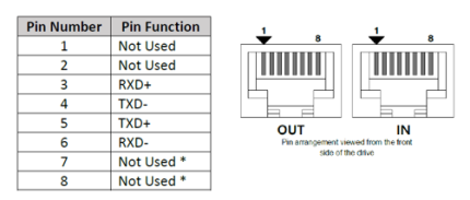
Pins 3, 4, 5, and 6 are on the L7P RJ45 connector labeled “IN”.
-
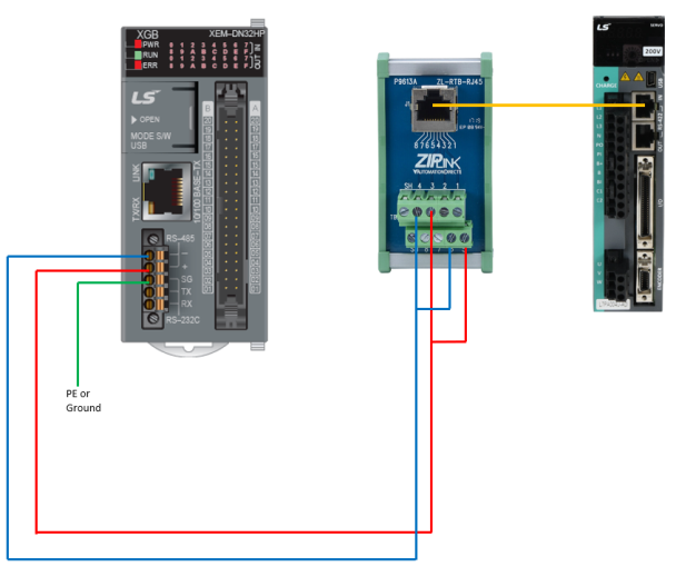
Strip back one side of an ethernet/RJ45 cable to connect the servo “IN” port to a PLC’s RS-485 terminals or use a ZL-RTB-RJ45 RJ45 breakout board.
-
For multiple drives, use a standard ethernet cable to connect the “OUT” RJ45 connector of the first drive to the “IN” connector of the next drive.
-
Connect multiple drives the same way with normal ethernet patch cables.
-
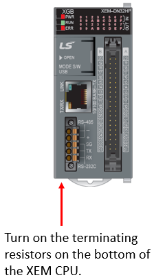
On the last drive in the system, set DIP switch #2 (located below the 7-segment LEDs) to ON to incorporate a 120Ω terminating resistor.
-
Additionally, it is important to make sure grounding/common is connected between drives and controller to avoid a floating differential voltage that may affect the communication.
L7P Pin-out diagram:
LP215-1