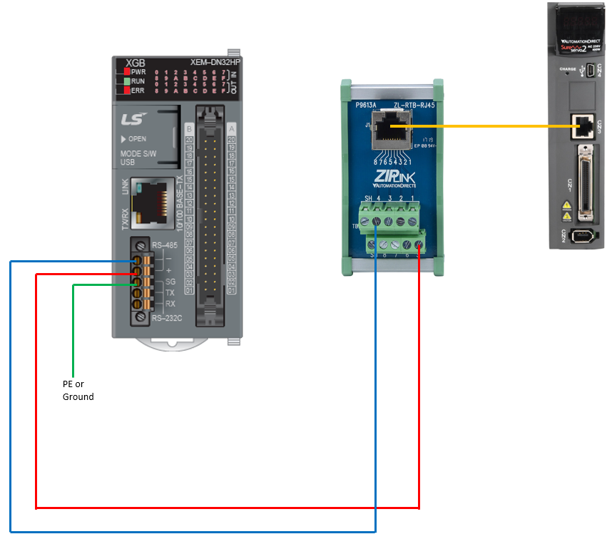
Wiring the XEM CPU to SureServo2 Drive
-
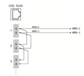
Pins 4 and 5 on the CN3 RJ45 connector on the SureServo2 drive are the + and – connections of the RS-485 connection.
-
Strip back one side of an Ethernet/RJ45 cable to connect the servo CN3 port to a PLC’s RS-485 terminals or use a ZL-RTB-RJ45 RJ45 breakout board.
-
For multiple drives, use a standard Ethernet cable to connect to the SV2-CN3-CON-2 SureServo2 splitter.
-
Connect multiple drives the same way with normal Ethernet patch cables.
-
On the last drive in the system, use SV2-CN3-TR2 to incorporate a 120Ω terminating resistor.
-
Additionally, it is important to make sure grounding/common is connected between drives and controller to avoid a floating differential voltage that may affect the communication.
CN3 Pin-out Diagram
Notes:
-
The cable length can be up to 100 meters when the servo drive is installed in a quiet environment. If the transmission speed is over 38400 bps however, a maximum 15 meter cable is recommended to ensure data transmission accuracy.
-
The numbers on the above figure represent the pin number of each connector.
-
When using RS-485 communication, you may connect up to 32 servo drives. You can install a repeater to connect more servo drives (the maximum is 127).
-
Please refer to the SureServo2 user manual on using SV2-CN3-CON-2 and SV2-CN3-TR2 to create an RS-485 network with minimal end-user wiring.
LP213-1