Connect to GS20 VFD with EtherNet/IP Implicit
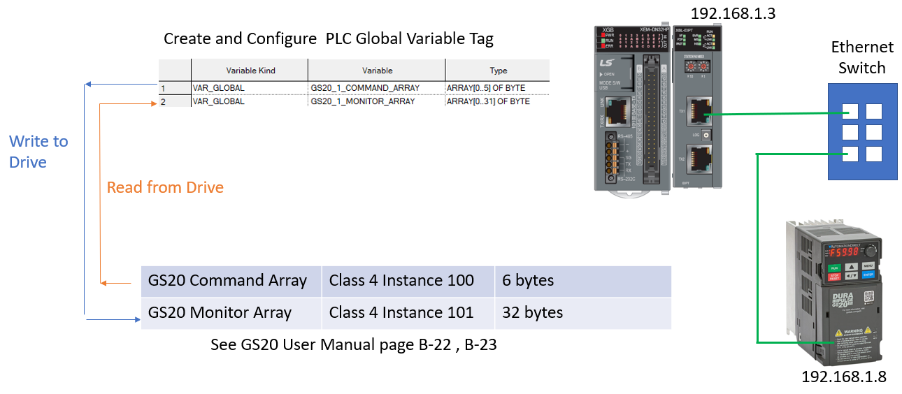
This procedure will walk through setting up read/write communications between the LS XEM PLC and GS20 AC Drive using the EtherNet/IP protocol.
EtherNet/IP communications is set through the Project configuration. No ladder programming is required for communications.
Key Steps:
-
Add Variable Tags for EIP Comms to GS20
-
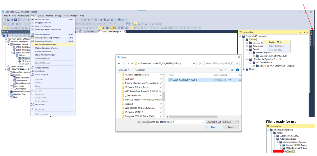
Register GS20 EDS file for use in the EIP Configuration.
-
Complete the P2P 03 EIP Configuration to set up communication.
-
Save and Download the program.
Process Overview
Connection Procedure
| Step | Action |
|---|---|
| 1 |
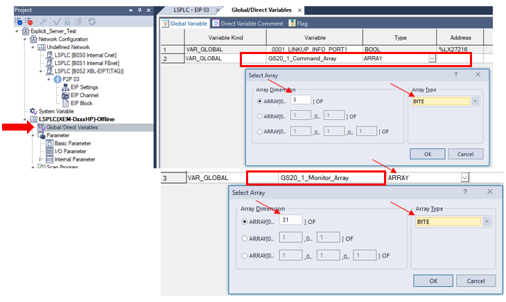
First, create the Variable tags that will be used for GS20 VFD data. Create 2 tag arrays for the EIP data :
Enter Tag name. Choose Array Data type and press Enter. Fill out the Array window with the number of registers and Array type (BYTE).
Tip: Double-click in Initial Value to add descriptions to individual array elements. Select the EIP/OPC UA box. This indicates the tag will be used for EtherNet/IP data, and allows it to show up in the EIP Block window.
|
| 2 |
Register the EDS file for use in the P2P 03 Network. The next step is to define the EtherNet/IP device with an EDS file. The GS20 AC Drive EDS configuration will be registered in XG5000. This will be referenced later when the network is configured.
|
| 3 |
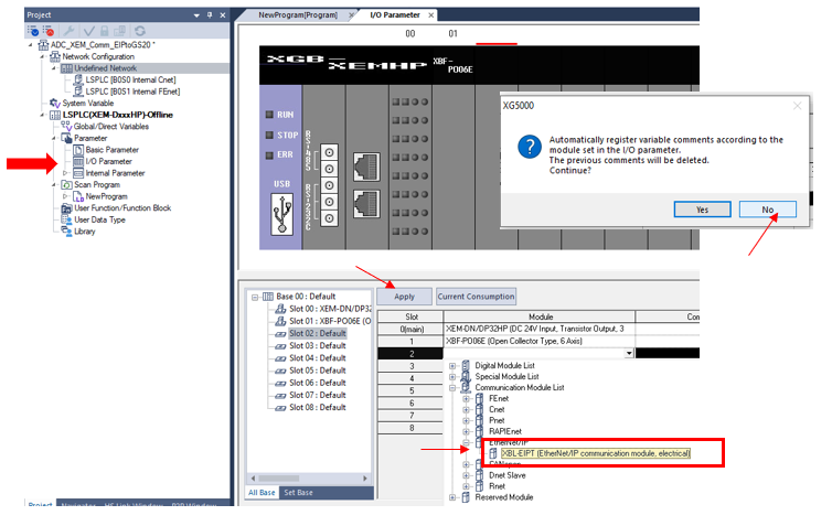
Add XBL-EIPT card to I/O Configuration.
|
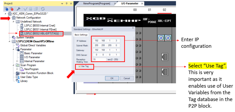
| 4 |
Configure the XBL-EIPT Card.
|
| 5 |
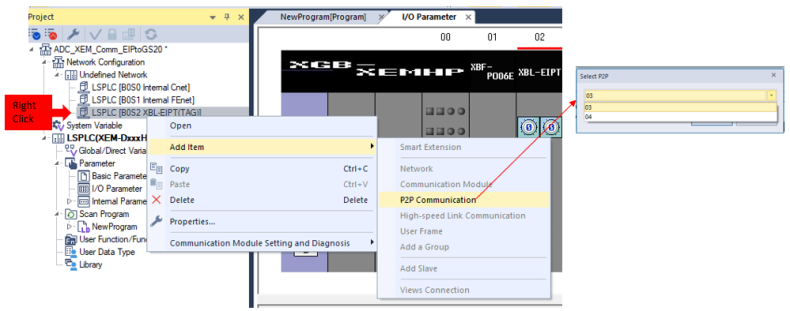
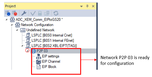
Add the EtherNet/IP P2P 03 Network.
|
| 6 |
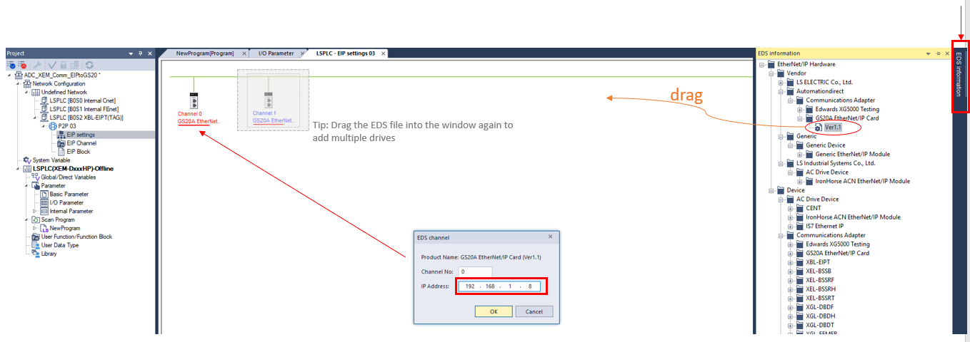
Drag the EDS file for use in the P2P 03 Network-EIP Settings Window.
|
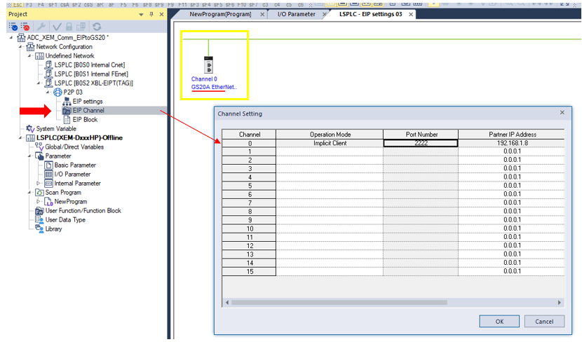
| 7 |
View the Channel window for the EtherNet/IP Configuration of the GS20 VFD. Notice that Channel 0 has been set up as an Implicit Client with the IP address assigned in EIP settings in the previous step.
The channel is now available for selection in the P2P Block window. |
| 8 |
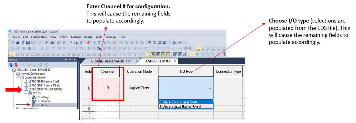
Use the EIP Block window to configure the EIP Communications to the GS20. Double-click EIP Block window and the LSPLC EIP 03 Block configuration window will open.
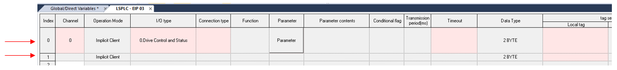
If 0. Drive Control and Status is selected, notice two index blocks are required for configuration, Control and Status.
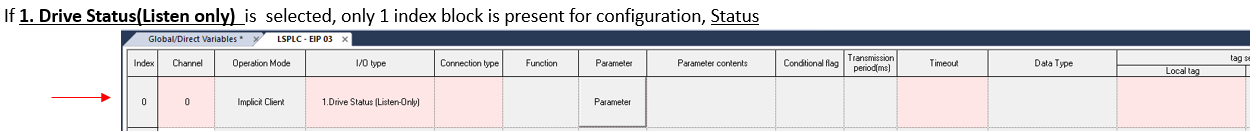
If 1. Drive Status (Listen only) is selected, only one index block is present for configuration, Status.
|
| 9 |
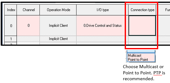
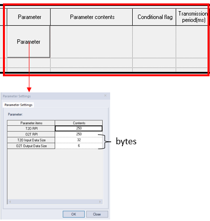
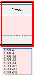
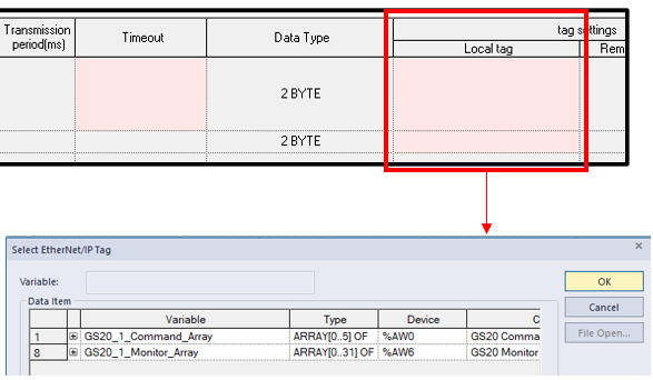
Set the EIP Block configuration fields. Drop down selections are populated based on EDS files.
The completed configuration will look similar to the example below. The Red highlight will be removed if all data is correct.
|
| 10 |
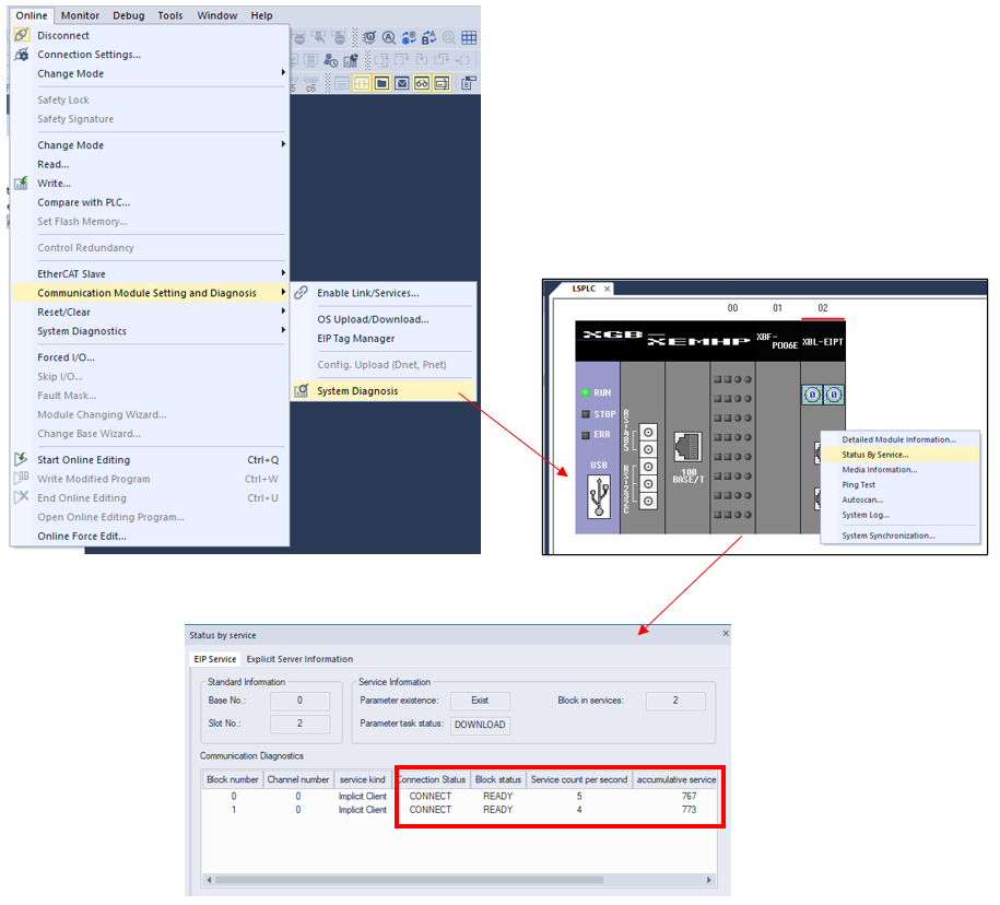
Write the program to the PLC and Monitor Status.
Monitor Status of the EIP communication.
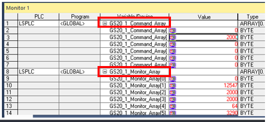
Add EIP Variables to the Monitor Window. Verify drive data is being transferred.
|


LP207