ModbusTCP Server Setup
Video Tutorial
Server Setup Steps
| Step | Action |
|---|---|
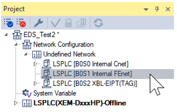
| 1 |
Open the Internal FEnet settings.
|
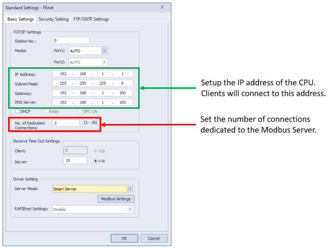
| 2 |
Setup FEnet parameters.
|
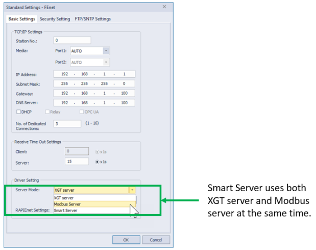
| 3 |
Choose Modbus Server or Smart Server as the Server Mode.
|
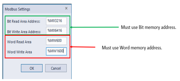
| 4 |
Press Modbus Settings button to configure memory address space for the server.
|
| 5 |
Configure Modbus Settings with appropriate memory addresses.
|
For this application example, ModbusTCP communication requires the following:
-
1,008 bits (read)
-
1,008 bits (coil)
-
1,000 words (read)
-
1,000 words (hold)
Note: Memory blocks of 1,008 and 1,000 are chosen as an example only. You can choose any memory block size for your needs.
| Step | Action |
|---|---|
| 1 | Choose the direct memory area in the LS PLC. In this example, the M memory area will be used. The user can choose the W area or a combination of both. |
| 2 |
Determine the blocks of registers that will be used.
|
| 3 |
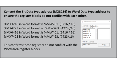
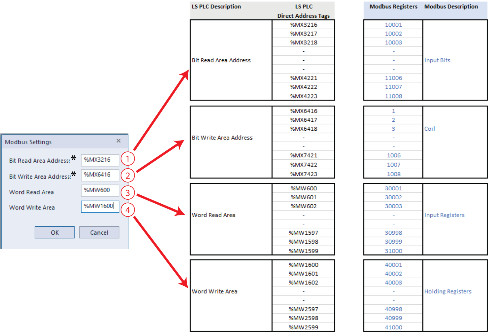
Enter the starting registers of each Modbus area (red above) in the Modbus settings window.
*Note: Bit area must use Bit data type address. |
| 4 | Select Ok Mapping will be as the chart indicates. |
LP201-1
