Using Generic EtherNet/IP Module EDS File
Video Tutorial
XG5000 provides a generic EtherNet/IP module EDS file to use with any EtherNet/IP device that supports implicit communication. This file comes with XG5000 and doesn’t need to be installed separately. The generic module EDS configuration requires the user to know these values:
-
Input Assembly Instance number
-
Input Assembly data size
-
Output Assembly Instance number
-
Output Assembly data size
-
Configuration Assembly Instance number
-
Configuration data size and data
Generic EtherNet/IP Module EDS Requirements:
-
Requires XG5000 4.76 or later.
-
Requires XEM CPU OS V2.40 or later.
-
Requires XBL-EIPT OS V2.40 or later.
The Use Tag option in the XBL-EIPT Configuration allows a user created variable to be used for EtherNet/IP implicit connection data.
| Step | Action |
|---|---|
| 1 |
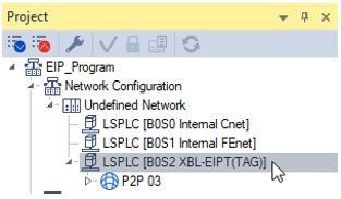
In your XG5000 project with the XBL-EIPT Configured, double-click on the XBL-EIPT under the Network Configuration.
|
| 2 |
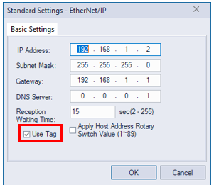
Enable the check next to Use Tag. Press OK to exit the configuration screen.
|
| Step | Action |
|---|---|
| 1 |
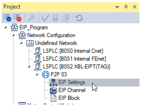
In your XG5000 project with the XBL-EIPT Configured, open EIP Settings.
|
| 2 |
In the EDS Information window, maximize Generic Device è Generic EtherNet/IP Module. Left-click and drag the Ver1.1 file to the EIP Settings Screen.
|
| 3 |
Enter the IP Address of the EtherNet/IP device and press OK. This example shows 192.168.1.9 as the IP address.
|
| Step | Action |
|---|---|
| 1 |
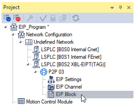
In your XG5000 project with the XBL-EIPT Configured, open EIP Block.
|
| 2 |
In an available Index row, enter the channel number of the Generic EtherNet/IP EDS file that was added to the EIP Settings. In our example it will be channel 0.
|
| 3 |
Choose the correct I/O type for the device. This example shows Exclusive Owner(16bit instance) and will use WORD data types for configuration and the data arrays.
|
| 4 |
Choose the Connection type. This example shows Point to Point so that EtherNet/IP packets for this device aren’t sent to all multicast devices.
|
| 5 |
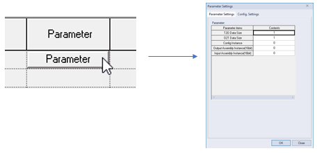
Press the Parameter button to configure the assemblies for this EtherNet/IP connection.
|
| 6 |
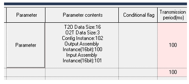
Enter the Parameter settings for your device. In this example, we will use the values from the GS20-CM-ENETIP communication card for the GS20 AC Drive.
|
| 7 |
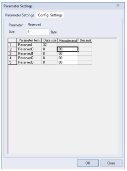
Select the Config. Settings tab to enter the configuration data for your device. Press OK when done.
|
| 8 |
Enter the Transmission period in milliseconds for the connection. This example is using 100 ms.
|
| 9 |
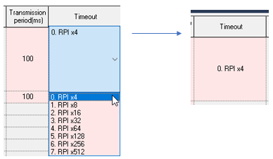
Select the Timeout setting for your application. This example uses RPI x4 so timeout would be 400ms.
|
| 10 |
Make sure to have variables declared for the input and output data. This example shows two arrays of WORD type to match the EIP block configuration sizes. Make sure the EIP/OPC UA column is checked for the variable.
|
| 11 |
Double-click in the top Local Tag section to add the variable created for the input data.
|
| 12 |
Double-click in the bottom Local Tag section to add the variable created for the output data.
|
| 13 |
The whole index row should have a white background if all settings are configured with a valid value.
|
LP200D
