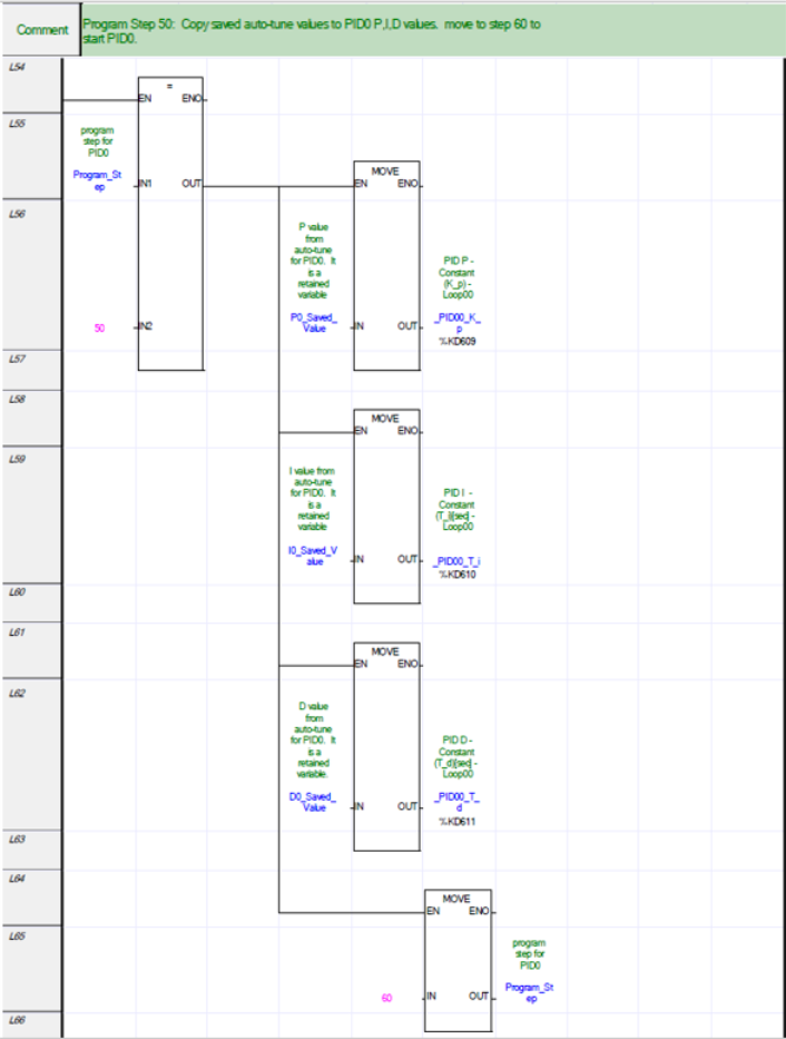
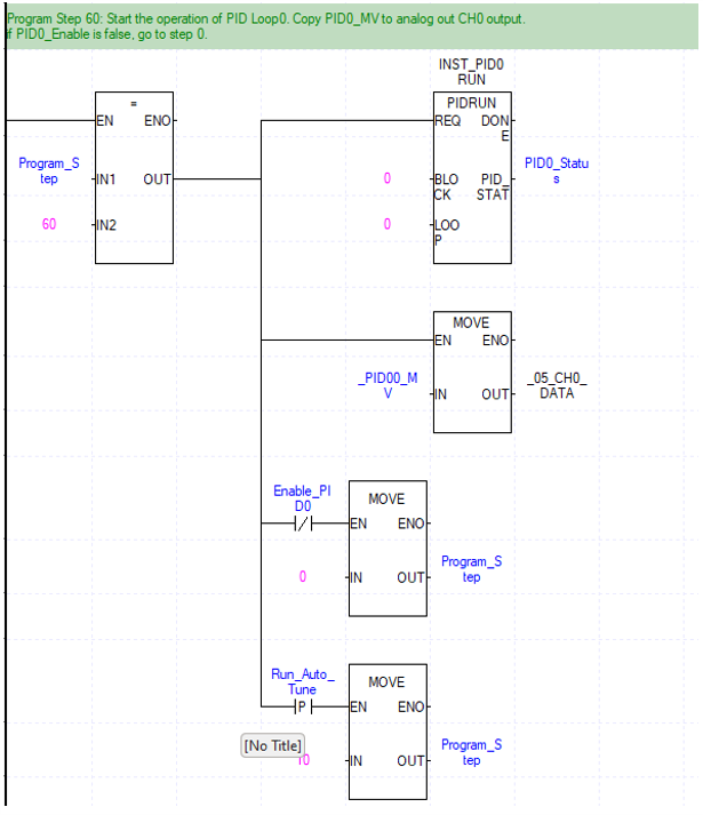
PID Ladder Diagram Program Example
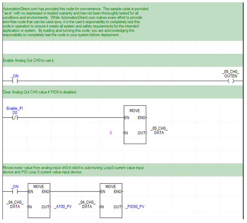
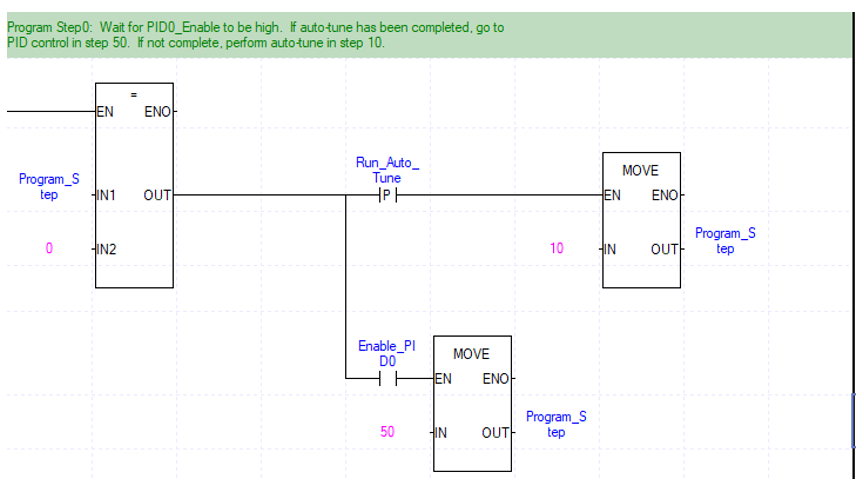
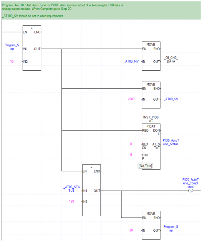
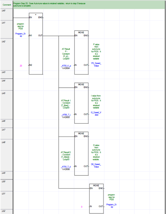
This Ladder diagram example shows a use of Auto-Tune and PID control for LOOP 0.
Notes:
-
Block Value for PID function blocks will always be 0.
-
See XG5000 help file for PIDAT status information.
-
See XG5000 help file for PIDRUN status and error information in the for XEC table.
| Variable Kind | Variables | Type | Address | Initial Value | Retain | Used |
EIP/ |
HMI | Comment | |
|---|---|---|---|---|---|---|---|---|---|---|
| 1 | VAR | D0_Saved_Value | REAL | ✓ | ✓ | D value from auto-tune for PID0. | ||||
| 2 | VAR | Enable_PID0 | BOOL | ✓ | Command to enable PID0. | |||||
| 3 | VAR | I0_Saved_Value | REAL | ✓ | ✓ | I value from auto-tune for PID0. | ||||
| 4 | VAR | INST_PID0AT | PIDAT | ✓ | Instance of auto-tune function block. | |||||
| 5 | VAR | INST_PID0RUN | PIDRUN | ✓ | Instance of PID0 run function block. | |||||
| 6 | VAR | P0_Saved_Value | REAL | ✓ | ✓ | P value from auto-tune for PID0. | ||||
| 7 | VAR | PID0_AutoTune_Co | BOOL | ✓ | ✓ | Status that auto-tune has been done for PID0. | ||||
| 8 | VAR | PID0_AutoTune_Stat | WORD | ✓ | Status word of the auto-tune function. | |||||
| 9 | VAR | PID0_Status | WORD | ✓ | Status word of PID0. | |||||
| 10 | VAR | Program_Step | USINT | 0 | ✓ | Program step for PID0. | ||||
| 11 | VAR | Run_Auto_Tune | BOOL | ✓ | Command to run auto-tune. | |||||
| 12 | VAR_EXTERNAL | _04_CH0_DATA | WORD | %UW0.4.2 | ✓ | Analog input module: CH0 output. | ||||
| 13 | VAR_EXTERNAL | _05_CH0_DATA | WORD | %UW0.5.3 | ✓ | Analog output module: CH0 input. | ||||
| 14 | VAR_EXTERNAL | _05_CH0_OUTEN | BOOL | %UX0.5.32 | ✓ | Analog output module: CH0 output enable. |
LP109-3
