Analog Output Module Configuration
Adding an analog module to XG5000 project:
| Step | Action |
|---|---|
| 1 |
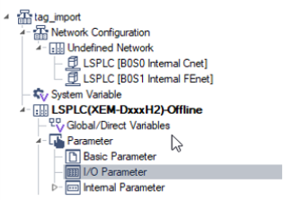
Open I/O Parameter in the XG5000 project.
|
| 2 |
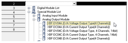
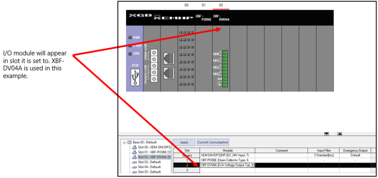
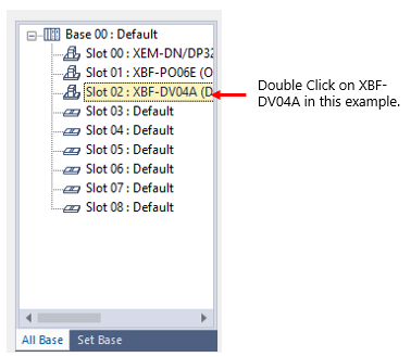
Insert analog I/O module in the slot it will be on the physical PLC rack. It is in Special Module List.
|
| 3 |
Press Apply to create the symbolic variables.
|
| 4 |
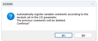
Press Yes to start creation of symbolic variables.
|
| 5 |
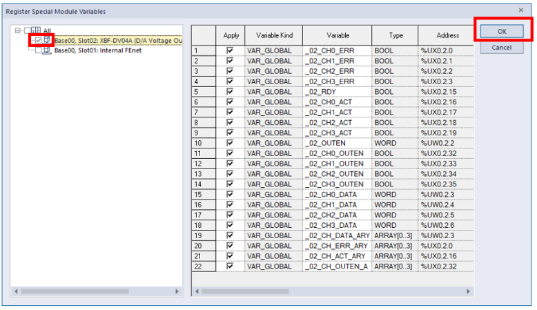
Check the slot where analog I/O module was added. Press OK to create symbolic variables.
|
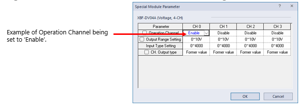
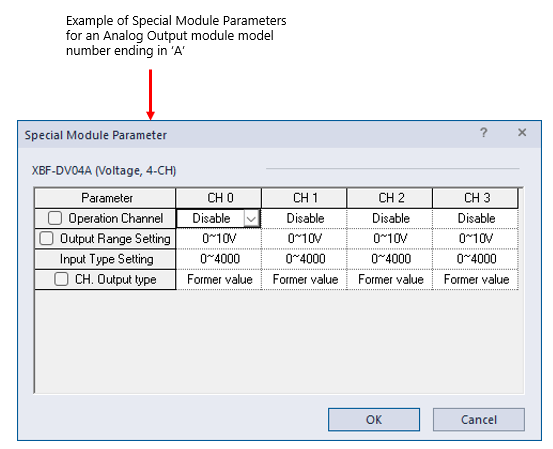
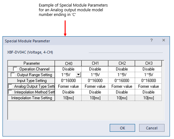
Open Special Module Parameter screen in the I/O Parameter window.
Each of the fields can be set for the channels on the analog output module.
| Parameter | Description |
|---|---|
| Operation Channel |
Select Enable to turn on the Channel or Disable to turn off the Channel. Automation Direct recommends only enabling channels that are going to be used.
|
| Output Range Setting |
Output Ranges will vary depending on the Analog Output Module being used.
|
| Input Type Setting |
Choose the scaling range of the Analog Output. Available options are 0-4000, -2000-2000, 0-1000, and 0-1000(%). The Analog output data will only be a value in the range chosen.
|
| CH. Output Type |
This sets the output value of a channel to chosen setting when CPU switches from RUN to STOP. Choices are Former Value, minimum value, middle value, or maximum value.
|
| Parameter | Description |
|---|---|
| Operation Channel |
Select Enable to turn on the Channel or Disable to turn off the Channel. Automation Direct recommends only enabling channels that are going to be used.
|
| Output Range Setting |
Output Ranges will vary depending on the Analog Output Module being used.
|
| Input Type Setting |
Choose the scaling range of the Analog Output. Available options are 0-16000, -8000-8000, 1000-5000, and 0-10000(%). The Analog output data will only be a value in the range chosen.
|
| Analog Output Type Setting |
This sets the output value of a channel to chosen setting when CPU switches from RUN to STOP. Choices are Former Value, minimum value, middle value, or maximum value.
|
| Interpolation Method Setting |
Select an interpolation method for the analog output. Options are Disable, Linear, S Curve. See LS User manual for more information on interpolation settings.
|
| Interpolation Time Setting |
This is the time setting for chosen interpolation setting method when it is not Disable. Options available are 10(ms), 100(ms), 1(s), and 60(s).
|
To output analog voltage/current from the output channel, you need to take the following 2 steps.
| Step | Action |
|---|---|
| 1 |
Set the Operation Channel to Enable in the Special Module Parameter window.
|
| 2 |
Set the Channel Output Enable boolean to TRUE or 1 in program code. The symbolic variables created by XG5000 can make this step simpler.
|
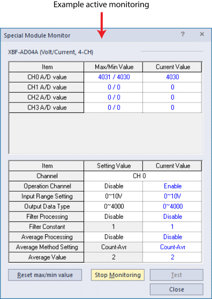
After getting online with the XEM CPU, the user can open Special Module monitoring to see current status of analog output channels.
| Step | Action |
|---|---|
| 1 |
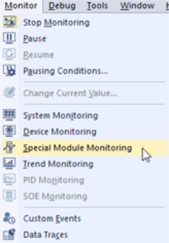
Open Monitor menuè Special Module Monitoring.
|
| 2 |
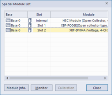
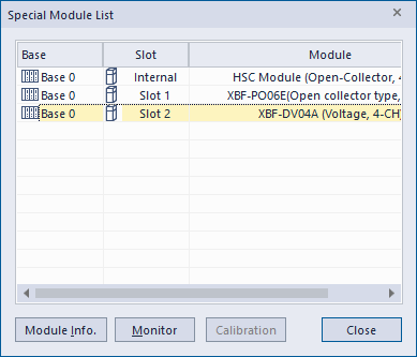
Select the slot the analog I/O module is in (in this example, Slot 2) .
|
| 3 | Press Monitor to open Special Module Monitoring. |
| 4 |
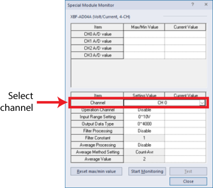
Select the Channel to monitor.
|
| 5 |
Press Start Monitoring.
|
| 6 | Press Stop Monitoring or Close when finished. |
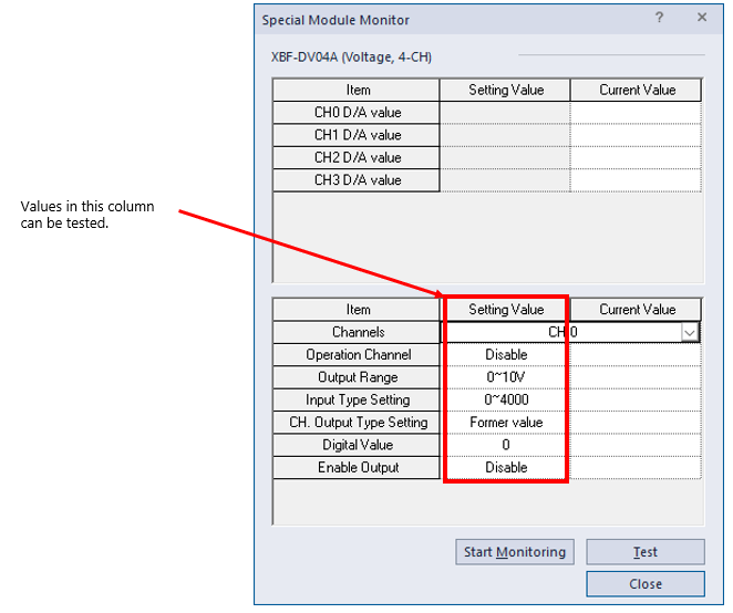
If the XEM CPU is in STOP mode, XG5000 allows analog input settings to be tested in the Special Module Monitor.
-
Change the setting to test in the Setting Value Column.
-
Press Start Monitoring.
-
Press Test to test new Setting Value.
-
This does not change module configuration. The I/O configuration must be done in the I/O Parameter screen.
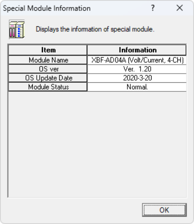
After getting online with the XEM CPU, the user can open System Monitoring to get module information for the analog I/O module.
| Step | Action |
|---|---|
| 1 | Open Monitor menu è Special Module Monitoring. |
| 2 |
Select the slot the analog I/O module is in (for this example, Slot 2) .
|
| 3 |
Press Module Info. to open Special Module Information Special Module information Shows:
|
There is an alternate method for getting to the Special Module Monitor and Special Module Info screens.
| Step | Action |
|---|---|
| 1 | Open Monitor menu è System Monitoring. |
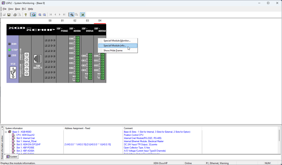
| 2 | Right-click on the Analog I/O Module. |
| 3 |
Select Special Module Info… or Special Module Monitor…
|
LP104-2
