Topic: CL181

| Send Instruction: MODBUS RTU |
Topic: CL181
|
The Send instruction allows you to use Com Port 2 or 3 (if available) on the CLICK CPU modules, or Com Port 1 or 2 of a C2-DCM module, as a network Master and write data to external devices. The CLICK CPU modules support the MODBUS (RTU) and ASCII protocols. This help topic covers the MODBUS protocol. Please refer to the help topic Send Instruction: ASCII for the ASCII protocol.
If you use a Com Port on the CLICK CPU modules as a MODBUS Slave, you don't need to use this instruction. Set up the Com Port to match the configuration of the MODBUS network and assign a unique Node Address.
|
|
Note: For the Com Port wiring information, please refer to the CLICK PLC Hardware Manual or CLICK PLUS PLC Hardware Manual.
Note: If you need more detailed information about the MODBUS protocol, we recommend to visit the following web site: http://www.MODBUS.org |
|
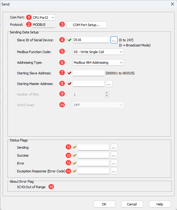
1 Com Port: Click the down arrow to select a Port from the available list. Port2 is default.
2 Protocol: This field displays the Protocol Type that is currently selected. The two choices are MODBUS and ASCII. To change from MODBUS to ASCII, see Item3.
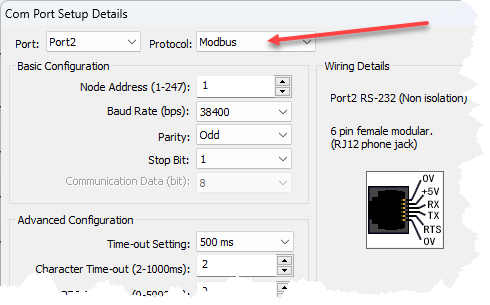
3 COM Port Setup: Click on this button to open the Com Port Setup window shown below. From this window click on the down arrow for the Protocol field and select ASCII or MODBUS.
|
|
Note: If the Protocol parameter is grayed out, it means that there is at least oneReceive or Send instruction assigned to the Com Port already. If you still want to change the Protocol, please delete those Receive/Send instructions first. |
|
4 Slave ID (0-247): Select the Node ID of the MODBUS Slave that you want to write data to, or select 0. Slave ID 0 is called Broadcast Mode. In the Broadcast Mode, the MODBUS Master can send a message to all Slaves in the network at the same time. In this mode, Slaves do not reply to the MODBUS Master. When you use this Broadcast Mode, please check if the Slaves in the network support this mode. The Slave ID may also be set using a DS Register. You can either enter a value or open the Address Picker to find an address. If the DS value is outside the range of 0-247, SC43 Out of range will be set TRUE.
|
|
Note: The CLICK PLC supports Broadcast Mode when it is used as a MODBUS Slave. |
|
5 MODBUS Function Code: Select one of the following MODBUS Function Codes:
05 - Write Single Coil
06 - Write Single Register
15 - Write Multiple Coils
16 - Write Multiple Registers
6 Addressing Type: Select one of the following MODBUS Addressing Types:
|
Addressing Type |
Explanation |
|
MODBUS 984 Addressing |
This Addressing is patterned after the Modicon PLC Addressing, which many devices support. 0***** are Coils (Read/Write) 4***** are Holding Registers (Read/Write) |
|
MODBUS Hex Addressing |
This Addressing is patterned after what the MODBUS protocol actually requests, which is simply a Function Code + an Offset. |
|
CLICK Addressing |
If the MODBUS Slave is the CLICK PLC, we recommend to use this CLICK Addressing because you can use the Address Picker to select the Starting Slave Address. |
7 Starting
Slave Address: Enter the Slave
Address to start writing data to. Here are the
valid Slave addresses.
If you selected the CLICK
Addressing, you can use the Address
Picker by clicking the ![]() icon.
icon.
|
MODBUS Addressing |
Function Code |
|||
|
05 |
06 |
15 |
16 |
|
|
MODBUS 984 |
1 to 65535 |
400001 to 465535 |
1 to 65535 |
400001 to 465535 |
|
MODBUS Hex |
0h to FFFEh |
0h to FFFEh |
0h to FFFEh |
0h to FFFEh |
|
CLICK |
Y and C |
DS,
DH, SD, TD, |
Y and C |
CTD, DS, DD, DH,
DF, SD, |
8 Starting Master Address:
Enter the Starting Memory
Address of the Master
CLICK CPU module to write the data to the MODBUS
Slave(s). You can use the Address
Picker by clicking the ![]() icon.
icon.
|
Function Code |
|||
|
05 |
06 |
15 |
16 |
|
X, Y, C, T, CT and SC |
DS, DH, XD, YD, TD, SD and TXT |
X, Y, C, T, CT and SC |
CTD, DS, DD, DH, DF, TD, SD and TXT |
9 Number of Bits/Master Addresses: Enter the size of the data to write to the MODBUS Slave(s).
10 Word Swap: When the Starting Master Address is a DH, TD, DS or SD Memory Address, this option is available. These Memory Addresses have 32 bit data length (2 Words), so each Address has data that can be written to two registers in the MODBUS Slave. You can Swap the order of those two word data in the DH, TD, DS or SD Memory Addresses to write to the Slave.
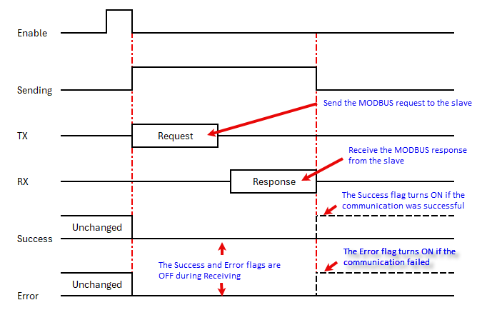
11 Sending: Assign a C bit as the Sending Flag. This C bit turns ON when the Com Port is Sending a write request to the MODBUS Slave(s) with this instruction. Please refer to the Timing Chartshown below.
|
|
Note: This Sending Flag is OFF when a Receive is reading data from a MODBUS Slave or another Send instruction is writing data to a MODBUS Slave(s). |
12 Success: Assign a C bit as the Success Flag. This C bit turns ON after the Com Port wrote data to the MODBUS Slave(s) successfully. It stays ON until this instruction is re-enabled. Please refer to the Timing Chartshown below.
|
|
Note: In the Broadcast Mode (Slave ID = 0), there is no response from the MODBUS Slaves. The Success bit turns ON automatically after the CLICK PLC executed the Send instruction. |
13 Error: Assign a C bit as the Error Flag. This C bit turns ON after the Com Port could not write data to the MODBUS slave(s) successfully. It stays ON until this instruction is re-enabled. Please refer to the Timing Chart shown below.
14 Exception Response (Error Code): Assign a DS or DD Memory Address to store the Exception Response from the MODBUS Slave.
15 About Error Flag If the Slave ID is outside the range of 0-247, SC43 - Out of Range will be set True
|
|
Note: Each MODBUS Slave supports a different set of the Exception Response. Please refer to the user manual/specifications of each MODBUS Slave. If you are using a CLICK PLC as a MODBUS Slave, please refer to this topic for the Exception Response that the CLICK PLC supports. |