
| C0-04DA-2 Settings |
|
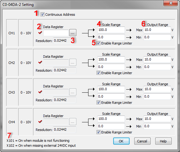
The C0-04DA-2 Setting dialog supports the customer to assign the DF memory addresses that store the analog values to output and set up the scaling for the analog output voltage.
![]()
1 Continuous Address: If you want to assign continuous DF memory addresses to store the analog values before scaling, please check this option. In this case, you just need to assign a DF memory address to CH1. The DF memory address will be the starting address of those continuous DF memory addresses.
2 Data Register : Enter a DF memory address to store the analog value before scaling it. In the CLICK PLC, all analog data are handled as floating point numbers. So you can select only DF memory addresses.
3 Resolution: The CLICK Software automatically calculates the resolution of the analog data before scaling according to the bit resolution of the analog output and the scaling setup, and displays the value here.
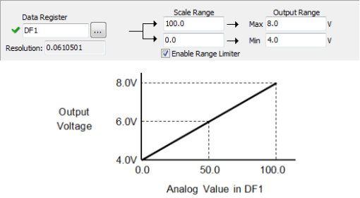
4Scale Range: Enter the maximum and minimum scaled values.
In the following example, the Scale Range is set to 0.0 - 100.0 and the Output Range is set to 4.0 - 8.0V. This means analog value 0.0 in DF1 memory address will be converted to output voltage 4.0V and analog value 100.0 will be converted to output voltage 8.0V. When the DF1 memory address has analog value 50.0, it will be converted to output voltage 6.0V.
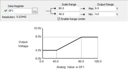
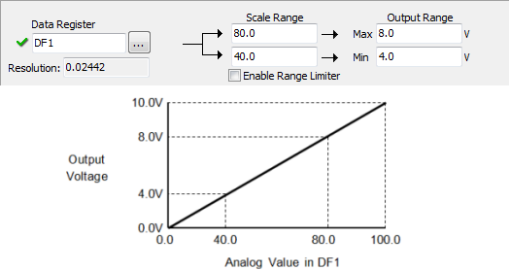
5Enable Range Limiter: By checking. this option, the analog values that are outside of the Scale Range will be adjusted to the minimum or maximum value of the Scale Range.
1. Enable Range Limiter is ON.
2. Enable Range Limiter is OFF.
6 Output Range: Enter the maximum and minimum Output Range after scaling.
7 X bit Addresses: You can use these X bit addresses to monitor the status of this analog output module.