Siemens Ethernet ISO over TCP/IP (S7-300/400) Setup |
Topic: CM209 |
The following information applies only to the Siemens Ethernet ISO over TCP/IP (S7-300) PLC compatible with C-more Panels.
The C-more panel is the master by default.
Locate PLC Configuration Information
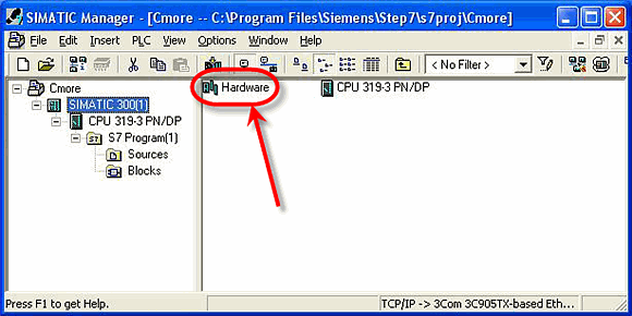
To Configure the PLC to communicate with the C-more Panel, you will first need to find the Port Settings for your Siemens PLC. To do this, open the SIMATIC Manager Software and project. From the SIMATIC Manager window, select the Hardware option located on the right side pane and indicated below.
When Hardware is selected, the HW Config (Hardware Configuration) window shown below will open.
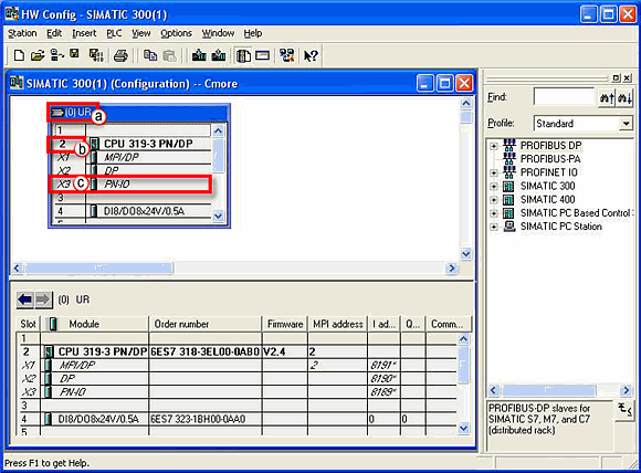
From the figure shown above:
- Note the Rack Number of the device you are trying to connect to. For the sample shown above, this Number is shown in parenthesis next to the text that says UR.
- Note the Slot Number listed. For the example shown above the Slot Number is 2. Both the Rack Number and Slot Number are necessary configuration parameters for the C-more Programming Software Panel Manager setup.
- Double click on the X3 PN-IO cell. This will open the Properties - PN-IO window shown below.
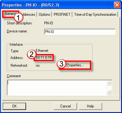
From the figure shown above:
- Make sure the General Tab is selected to see the details shown above.
- The current PLC IP Address will be displayed on this location.
|
|
Note: If using a communications module, use the IP Address of the communications module in place of the PLC IP Address. |
- Click on the Properties button to see more details on the IP Configuration. When selected, the Properties window shown below will open.
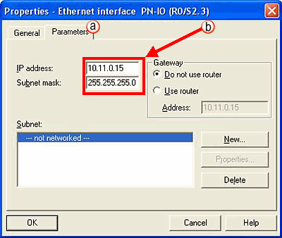
- Click on the Parameters Tab to select it.
- This window displays the IP Address and Subnet Mask settings for the PLC. This is the IP Address to enter in the C-more Programming Software Panel Manager setup window. Be sure that the Subnet Mask shown matches the Subnet Mask of the C-more Panel.
C-more Protocol Manager Settings
- Do one of the following:
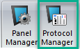
- Click the Protocol Manager button on the Home tab
— or — - Click the Protocol Manager button on the Setup tab
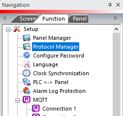
— or — - from the Navigation window, click the Function tab, click Setup and then select Protocol Manager.
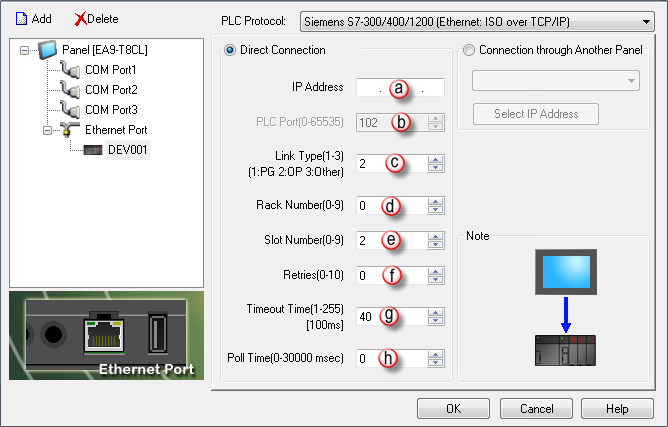
- From the Protocol Manager window, click the Device name on the tree to the left.
- The Device Setup window opens.
- From the PLC Protocol field, click on the down arrow
 and select Siemens S7-300 (Ethernet : ISO over TCP/IP).
When you select a different PLC Protocol than the one currently in use, the warning Message shown below appears.
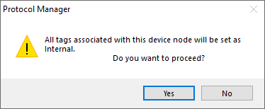
- Click Yes to accept.
All of the following settings must be set the same as the settings in Panel Manager in the C-more Programming Software. The C-more Panel Manager is shown above with the Siemens Ethernet S7-300 driver selected.
Use the SIMATIC Software screen on the top of this page as reference. Configure the Panel Manager as follows:
- IP Address: This is the IP Address of the S7-300 or S7-400 CPU (319-3). The IP Address can be found in the PN-IO parameter setting of the CPU in the SIMATIC Hardware configuration tool (shown above).
- PLC Port (0-65535): TCP port at the PLC. This setting is not configurable.
|
|
Note: If using a communications module, use the IP Address of the communications module in place of the PLC IP Address. |
- Link Type (1-3): This selects what Link Type the C-more Panel will be. Most of the times, this should be left at 2 (OP). There are limited numbers of connections for each Link Type that can be connected to the PLC. If that limit has been reached with the OP Link to the CPU, a different Link Type can sometimes be used. Refer to the Siemens documentation for the limitations of the various Link Types.
- Rack Number (0-9): This is the Rack Number of the CPU that is being targeted by C-more. Refer to the SIMATIC Hardware Configuration setting discussed above for this value.
- Slot Number (0-9): This is the Slot Number of the CPU that is being targeted by C-more. Refer to the SIMATIC Hardware Configuration setting for this value.
- Retries (0-10): This is the Number of Times that the Panel will Retry to send a Message if the request does not receive a reply in the specified Timeout Period. Once the Retry Count has been reached, the Panel will show an Error on the screen and begin trying to send messages again.
- Timeout Time (1-255): This is the amount of Time (in 100 millisecond units) that the Panel will wait on a Reply after sending a Request. Once the Timeout Timer expires, it will then Retry.
- Poll Time (0-30000): This is the amount of Time (in milliseconds) that the Panel will wait in between each Request.
