Mitsubishi Q/QnA Serial PLC Setup |
Topic: CM485 |
Pay close attention to the compatibility matrix, configuration details, and limitations provided in this topic. The Mitsubishi CPU types each have specific communication nuances that must be considered.
The following information applies only to the Mitsubishi Q/QnA Serial PLC compatible with C-more Panels. This driver can be used to connect to the Serial Port on the CPU for the Q00 CPU and the Q01 CPU only. For other Q Series CPU, a Serial Communications Module can be used with this driver. Refer to Mitsubishi Q Series Compatibility Matrix to see what driver to use for the various CPU and Communications Modules in the Mitsubishi Q series.
The Serial Communications Modules supported for this driver are:
- QJ71C24
- QJ71C24-R2
- QJ71C24N
- QJ71C24N-R2
- QJ71C24N-R4
The C-more panel is the master by default.
|
|
Note: Remember to power cycle the PLC after making changes to the communication port settings. |
View the PLC Serial Ports Settings
To Configure the Mitsubishi Q/QnA Serial PLC to communicate with the C-more Panel, you will first need to find the Port Settings for your Mitsubishi PLC. To do this, open the MELSOFT Software and double-click on the PLC Parameter icon on the left side panel of the MELSOFT Software as shown below.
When PLC Parameter is selected, the Q Parameter Setting window shown below will open.
Connect to the Q00 and Q01 CPU Serial Ports
To connect to the CPU Serial Ports of the Q00 CPU and the Q01 CPU, click on the Serial Tab so the Serial Communication is displayed as shown above. Set the following:
- Use Serial Communication: Tick the box to select this option.
- Transmission Speed: Click on the down arrow to display the Transmission speeds available and select the desired Speed. This is the same as the Baud Rate value setting of the C-more Programming Software's Panel Manager window. The Baud Rate and the Transmission Speed MUST MATCH.
- Sum Check: Tick the box to select the Sum Check option.
- Transmission Wait Time: Leave this setting on the default "No Waiting Time".
- RUN Write Setting: Tick the Permit box the to turn this option ON.
You must remember to use STYLE4 for the Protocol setting in the C-more Protocol Manager window discussed below when connecting to the Q00 or Q01 CPU directly.
Using the QJ71C24 Module
To use the QJ71C24 module, from the Q Parameter Setting window shown above, select the I/O Assignment Tab. The I/O Assignment available options are shown below.
|
|
Note: The PLC will return an Error if you attempt Writes to the X or Y memory area that has been assigned to the communication module in the StartXY column |
From this window, click on the Switch Setting button highlighted on the graphic above. This will open the Switch Setting window that will allow you to view the Serial Module parameters as shown below. This graphic includes call-outs that show what each value refers to.
- The column labeled Switch 1 contains the Setting for Channel 1 Baud Rate and Transmission Settings. The High Byte highlighted in the graphic above with yellow, contains the Baud Rate and the Low Byte highlighted in the graphic above with green, contains the Transmission Settings. The charts below explain these Settings(fields in gray are invalid choices for C-more):
| Baud Rate | High Byte value (Bits 15 to 8) |
|---|---|
| 50 | 0x0F |
| 300 | 0x00 |
| 600 | 0x01 |
| 1200 | 0x02 |
| 2400 | 0x03 |
| 4800 | 0x04 |
| 9600 | 0x05 |
| 14400 | 0x06 |
| 19200 | 0x07 |
| 28800 | 0x08 |
| 38400 | 0x09 |
| 57600 | 0x0A |
| 115200 | 0x0B |
| 230400 | 0x0C |
| Low Byte value | ||||||||
|---|---|---|---|---|---|---|---|---|
| Setting | Bit 7 | Bit 6 | Bit 5 | Bit 4 | Bit 3 | Bit 2 | Bit 1 | Bit 0 |
| Change Setting |
Write During Run | Checksum Code | Stop Bit | Parity | Data Bit | Operation Setting | ||
| 0 | Disabled | Disabled | No | 1 bit | 00 = No Parity 10 = No Parity 01 = Odd Parity 11 = Even Parity |
7 bits | Independent | |
| 1 | Enabled | Enabled | Yes | 2 bits | 8 bits | Linked | ||
| 1 | 1 | 1 | 0 | 0 | 0 | 0 | 1 | |
Looking at the Example graphic above before the tables, Switch 1 setting is 0x09E2. This would set the Channel 1 Seri0al Port on the module to 38400 Baud Rate, 1 Stop Bit, No Parity and 8 Data bits.
Where 0x09E2 breaks down as follows:
| 0x09 = | 38400 | (From the High Byte value Table Above) | 0x09 = | 38400 |
|---|---|---|---|---|
| (From the Low Byte value Table Above) | (From the Low Byte value Table Above) | (From the Low Byte value Table Above) | (From the Low Byte value Table Above) | (From the Low Byte value Table Above) |
| 0xE = | Bit 7 | Bit 6 | Bit 5 | Bit 4 |
| 1 | 1 | 1 | 0 | |
| Change Setting = Enabled | Write During Run = Enabled | Checksum Code = Yes | Stop Bit = 1 Bit | |
| Note: Bits 5, 6 and 7 must be 1 for C-more Communications. | ||||
| 0x2 = | Bit 3 | Bit 2 | Bit 1 | Bit 0 |
| 0 | 0 | 1 | 0 | |
| No Parity | Data Bit = 8 Bits | Operation Setting = Independent | ||
| Note: Bit 0 must be 0 for C-more Communications. | ||||
- Switches 2 and 4 are for the Communications Protocol Settings of Channel 1 and Channel 2 respectively. Set this field to 0001 for STYLE1 or set to 0004 for STYLE4. These are the only two settings that will work with C-more. Refer to Mitsubishi documentation for the other available options and their meanings.
C-more Protocol Manager Settings
- Do one of the following:
- Click the Protocol Manager button on the Home tab
— or — - Click the Protocol Manager button on the Setup tab
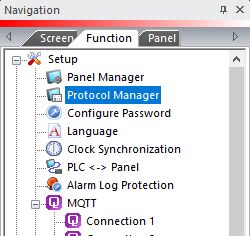
— or — - from the Navigation window, click the Function tab, click Setup and then select Protocol Manager.
- From the Protocol Manager window, click the Device name on the tree to the left.
- The Device Setup window opens.
- From the PLC Protocol field, click on the down arrow
 and select Mitsubishi Q/QnA Serial.
When you select a different PLC Protocol than the one currently in use, the warning Message shown below appears.
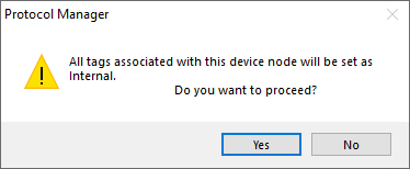
- Click Yes to accept.
Match these settings with Protocol Manager in the C-more Programming Software.
Use the MELSOFT Software information on the top of this page as reference.
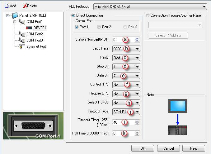
PLC Protocol Settings
a. Station Number
The PLC Address of the PLC Port where the C-more Panel is connected. Refer to Switch 5 setting above.
b. Baud Rate
Match the Baud Rate setting in either the Switch 1 or Switch 3 setting above (depending upon the connecting port).
c. Parity
Match the Parity setting in either the Switch 1 or Switch 3 setting above (depending upon the connecting port.)
d. Stop Bit
Match the Stop Bit setting in either the Switch 1 or Switch 3 setting above (depending upon the connecting port).
e. Data Bit
Match the Data Bit setting in either the Switch 1 or Switch 3 setting above (depending upon the connecting port).
f. Control RTS
Select Yes for the C-more panel to sense if the RTS signal line is controlled from the PLC port. Also, select Yes if the RS-422 driver signal needs to be turned OFF at the end of transmission. The default is No, based on connecting to a port with the RTS and CTS signals jumpered together.
g. Require CTS
Select Yes in this drop-down If using a modem on the C-more serial port for flow control. Otherwise, leave this setting at No.
h. Select RS485
Select Yes in this drop-down if you need 2 wire RS 485 communication. The default is No, based on connecting to a port with the RTS and CTS signals jumpered together.
Along with selecting Yes in this field, you must jumper the SD+ and RD+ along with the SD- and RD- pins. This setting is on by default since the GS Drives use 2 wire RS-485 as their method of serial communication.
i. Protocol Type
Match the Switch 2 or Switch 4 setting of the serial port (depending upon the connecting port).
Refer to the explanation above for Switch 2 and 4.
j. Timeout time (1-255) [100msec]
The time (in 100 millisecond increments) the C-more Panel waits for communications with the PLC before it displays an error. When the timer expires, the panel retries. 30 tenths of a second (3 seconds) is the default and should not require adjustment.
k. Poll Time
The amount of time (in milliseconds) that the panel will wait in between each request.
