Siemens S7-200 PPI PLC Setup |
Topic: CM478 |
The following information applies only to the Siemens S7-200 PPI PLC compatible with C-more Panels.
The C-more panel is the master by default.
Locating the Siemens S7-200 Configuration Information
To Configure the S7-200 PPI PLC to communicate with the C-more Panel, you will first need to find the Port Settings for your Siemens PLC.
- Open the Step 7-Micro/WIN Software and select the System Block icon on the left side panel of the Step 7 Software as shown below.
- This will open the System Block window, which is also shown below.
With the System Block window open to use as reference, continue to the C-more Programming Software to Configure the Panel Manager as discussed below.
C-more Protocol Manager Settings
- Do one of the following:
- Click the Protocol Manager button on the Home tab
— or — - Click the Protocol Manager button on the Setup tab
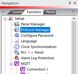
— or — - from the Navigation window, click the Function tab, click Setup and then select Protocol Manager.
- From the Protocol Manager window, click the Device name on the tree to the left.
- The Device Setup window opens.
- From the PLC Protocol field, click on the down arrow
 and select Siemens S7-200 (Serial : PPI).
When you select a different PLC Protocol than the one currently in use, the warning Message shown below appears.
- Click Yes to accept.
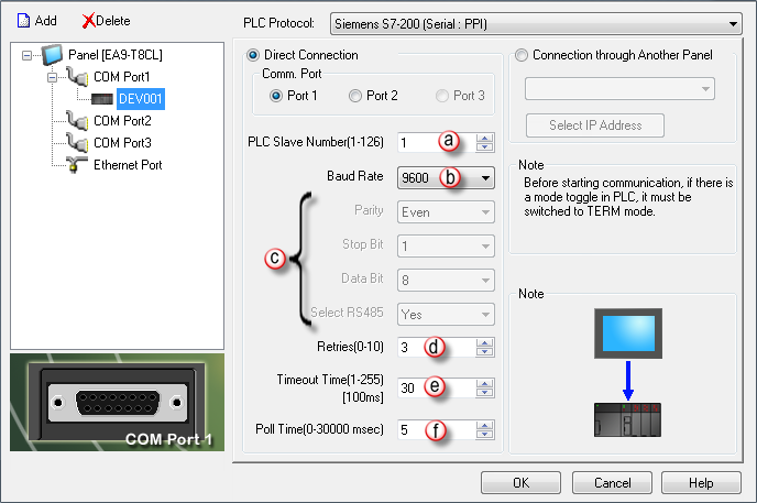
Match these settings with Protocol Manager in the C-more Programming Software.
Use the Step 7-Micro/WIN Software screen on the top of this page as reference. Configure the Panel Manager as follows:
- PLC Slave Number: This is the PLC Address of the PLC Port to which that the C-more Panel connects.
|
|
Note: In the Step7 MicroWin Software, the settings for the Ports are displayed from left to right, meaning that Port 0 is on the left and Port 1 is on the right, as shown on the Step 7 graphic on the top of this page. However, on the physical PLC itself, Port 1 is on the left and Port 0 is on the right. |
- Baud Rate: This setting should match the Baud Rate set in the System Block screen for the appropriate Port. The choices are 9600 or 19200.
- Parity, Stop Bit, Data Bit and Select RS485: These items are not adjustable from this window and are display only.
- Retries: This is the number of times that the Panel will Retry to send a Message if the request does not receive a Reply in the specified Timeout period. Once the Retry count has been reached, the Panel will show an Error on the screen and begin trying to send messages again.
- Timeout Time: This is the amount of Time (in 100 milliseconds) that the Panel will wait on a Reply after sending a request. Once the Timeout Timer expires, it will then Retry.
- Poll Time: This is the amount of Time (in milliseconds) that the Panel will wait in between each request.
