GE Ethernet SRTP — Fanuc Series R-30iB Protocol Setup |
Topic: CM370 |

The C-more panel is the master by default.
C-more Protocol Manager Settings
- Do one of the following:
- Click the Protocol Manager button on the Home tab
— or — - Click the Protocol Manager button on the Setup tab
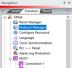
— or — - from the Navigation window, click the Function tab, click Setup and then select Protocol Manager.
- From the Protocol Manager window, click the Device name on the tree to the left.
- The Device Setup window opens.
- From the PLC Protocol field, click on the down arrow
 and select Fanuc Series R-30iB Robot Controller.
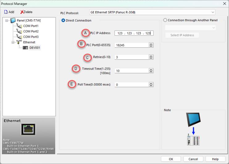
- IP Address: The IP Address of the Fanuc Series R-30iB Robot Controller.
- Port (0–65535): The SRTP server listening TCP port number of the PLC. The default value is 18245. This field can be changed in the event that the C-more panel needs to access the PLC through a firewall using NAT. This field can also be changed if there is a requirement to have the SRTP server port number at a non-default value on a LAN.
- Retries (0-10): The C-more panel will send a request to the Fanuc Series R-30iB Robot Controller. If the CPU does not reply within the specified “Response Timeout” period, the C-more panel will send the request again up to the number of Retries. Once the retry count (specified in this field) limit has been reached, the C-more panel will display a PLC Timeout error on the screen. This will occur on a TCP connect request or a Command request (after the TCP connection is established).
- Timeout time (1-255) (in 100ms units): The amount of Time (in 100ms units) that the panel will wait on the Command reply (or TCP ACK message) after sending a request. After the Timeout timer expires, it will then retry.
- Poll Time (0-30000 msec): The amount of Time (in milliseconds) that the panel will wait in between each request.
Fanuc Robot Controller Settings
To setup CM5 for use with Fanuc Series R-30iB Robot Controller, configure the following robot settings:
- On the Fanuc Teach Pendant, press the MENU button.
- Use the UP/DOWN arrows to move the highlighted block to 0 --NEXT -- and press ENTER (or press 0 on the keypad).
- Move the highlighted block to 6 SYSTEM and press ENTER (or press 6 on keypad).
- Move the highlighted block to 2 VARIABLE and press ENTER (or press 2 on keypad).
- Move the highlighted block to [$SNPX_PARAM] (holding shift allows you to scroll faster) and press ENTER.
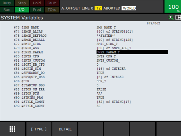
- Move the highlighted block [$NUM_CIMP] and press ENTER.
- Use the keypad to change the value to 2 and press ENTER.

- On the Fanuc Teach Pendant, press the MENU button.
- Use the UP/DOWN arrows to move highlighted block to 6 SETUP and press ENTER (or press 6 on the keypad).
- Move the highlighted block to 0 --NEXT -- and press ENTER (or press 0 on the keypad).
- The SETUP 2 page opens.
- Move the highlighted block to 7 HOST COMM and press ENTER (or press 7 on keypad).
- Move the highlighted block to 1 TCP/IP and press ENTER.
- Move the highlighted block to first available entry under HOST NAME (LOCAL).

- Use the Fanuc Teach Pendant keyboard to name your HMI.
- Use the LEFT/RIGHT arrows to move the highlighted block to INTERNET ADDRESS.
- Use the Fanuc Teach Pendant keyboard to enter your CM5 HMI IP address.
- Press FCTN button on the Fanuc Teach Pendant.
- Use the UP/DOWN arrows to move highlighted block to 0 --NEXT -- and press ENTER (or press 0 on the keypad).
- T he FUNCTION 2 page opens.
- Move highlighted block to 8 CYCLE POWER and press ENTER (or press 8 on the keypad).
- Select YES with the touch screen or press ENTER.
- Your robot will cycle power and should accept the new incoming connection to you CM5 HMI panel.
Cables and Wiring Diagrams
This opens a web page with the PDF version of the C-More Protocol Manager, Chapter 6, PLC Communications. Chapter 6 includes cables and wiring diagrams.
|
|
Note: An active internet connection is required to view. |
