GE Ethernet 90/30 and Rx3i SRTP Protocol Setup |
Topic: CM357 |
The C-more panel is the master by default.
C-more Protocol Manager Settings
- Do one of the following:
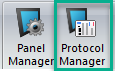
- Click the Protocol Manager button on the Home tab
— or — - Click the Protocol Manager button on the Setup tab
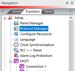
— or — - from the Navigation window, click the Function tab, click Setup and then select Protocol Manager.
- From the Protocol Manager window, click the Device name on the tree to the left.
- The Device Setup window opens.
- From the PLC Protocol field, click on the down arrow
 and select GE Ethernet SRTP (90/30 Rx3i).
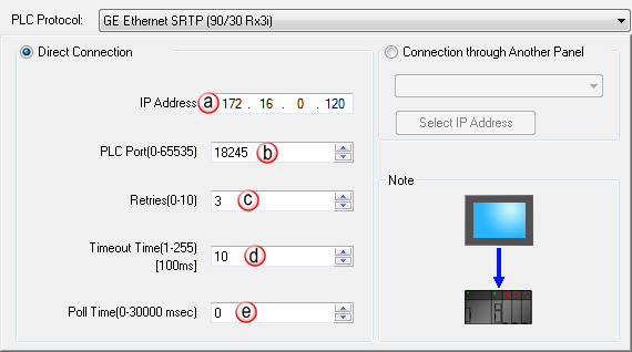
- IP Address: This is the IP Address of the GE Ethernet CPU. It can be found using the Proficy Machine Edition software (see below).
- Port (0–65535): This is the SRTP server listening TCP port number of the PLC. The default value is 18245. This field can be changed in the event that the C-more panel needs to access the PLC through a firewall using NAT. This field can also be changed if there is a requirement to have the SRTP server port number at a non-default value on a LAN.
- Retries (0-10): The C-more panel will send a request to the GE Ethernet CPU. If the CPU does not reply within the specified “Response Timeout” period, the C-more panel will send the request again up to the number of Retries. Once the retry count (specified in this field) limit has been reached, the C-more panel will display a PLC Timeout error on the screen. This will occur on a TCP connect request or a Command request (after the TCP connection is established).
- Timeout time (1-255) (in 100ms units): This is the amount of Time (in 100ms units) that the panel will wait on the Command reply (or TCP ACK message) after sending a request. After the Timeout timer expires, it will then retry.
- Poll Time (0-30000 msec): This is the amount of Time (in milliseconds) that the panel will wait in between each request.
Using Proficy Machine Edition Method to see IP Address
To Setup the GE 90/30 using the GE Cimplicity Programming Software, follow these steps:
Go to the Project Navigator and double-clickon the CPU slot (IC693CPU374). In the settings window of the CPU, click on the Ethernet tab to locate the IP Address and Subnet Mask:

Cables and Wiring Diagrams
This opens a web page with the PDF version of the C-More Protocol Manager, Chapter 6, PLC Communications. Chapter 6 includes cables and wiring diagrams.
|
|
Note: An active internet connection is required to view. |
