Allen-Bradley Generic EtherNet/IP Implicit Messaging Setup |
Topic: CM332 |
The following information applies for Allen-Bradley PLC for the purpose of setting up Implicit I/O Messaging via EtherNet/IP. The models included for this setup are (this setup applies only to these):
- ControlLogix 1756-EBNT & 1756-ENET/B
- CompactLogix with Built-in EtherNet/IP
The C-more panel is a SLAVE when communicating via Allen-Bradley EtherNet/IP Server (Generic IO Messaging) (Control/CompactLogix).
C-more Protocol Manager Settings
- Do one of the following:
- Click the Protocol Manager button on the Home tab
— or — - Click the Protocol Manager button on the Setup tab
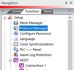
— or — - from the Navigation window, click the Function tab, click Setup and then select Protocol Manager.
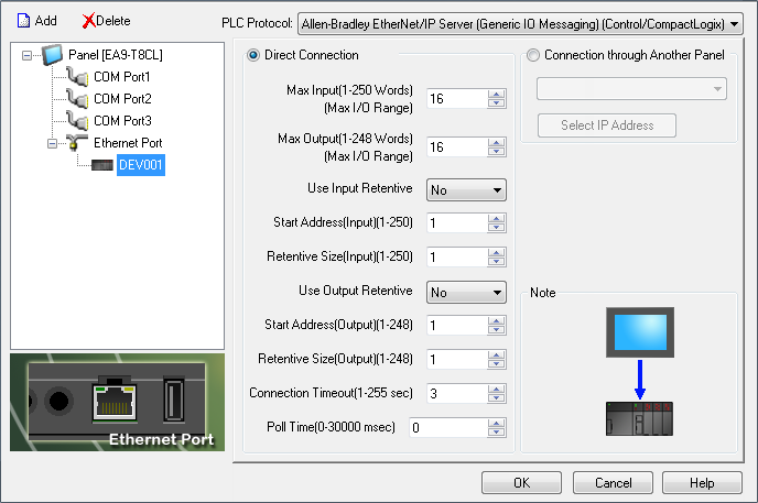
- From the Protocol Manager window, click the Device name on the tree to the left.
- The Device Setup window opens.
- From the PLC Protocol field, click on the down arrow
 and select Allen-Bradley EtherNet/IP Server (Generic IO Messaging) (Control/CompactLogix).
When you select a different PLC Protocol than the one currently in use, the warning Message shown below appears.
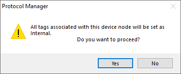
- Click Yes to accept.
All of the following settings must be set the same as the settings in Panel Manager in the C-more Programming Software. The C-more Panel Manager is shown above with the Generic EtherNet/IP driver selected.
- In I/O Configuration on the left panel of the window, right-click on Ethernet Module (1756-ENET/B EnetB) indicated on the graphic below.
|
|
Note: You must first add this module in the PLC I/O configuration. See your Allen-Bradley representative for more information on setting up your I/O configuration. |
- Right-click on the Ethernet Module.
- From the drop-down menu select Module Type.
- The window shown below opens.
- From this window, select Generic Ethernet Module
- Click on OK.
- Once the Module is selected, the Module Properties window shown below opens.
- On the Name field, type in a Name for this panel
- For the Comm Format field, select Data-INT. (See section below - Data Format for Other Data Formats).
- For the IP Address, enter the IP Address for the C-more Panel.
- For the Assembly Instance parameters, type in the following:
- Input = 100
- Output = 150
- Configuration =
|
|
Note: The parameters listed for Assembly Instant: Input are always the same and never change. |
- For the Size parameters, select the following:
- Configuration = 0
- Input (# of Words): Matches the Maximum Input field in the C-more Panel Manager setup if Data-INT is selected.
- Output (# of Words): Matches the Maximum Output field in the C-more Panel Manager setup if Data-INT is selected. If Data-DINT is selected, the PLC Input size must be one-half the Panel Maximum Input and the PLC Output size must be one-half the Panel Maximum Output
- Click on the Finish button.
Verify Setup
- To verify the Setup, in the left navigation window of the screen shown below, click on Task > Main Task > Main Program
- Select Program Tags.
- In the Scope drop-down, click the down arrow and select the Project Name (Controller) for the Controller Tags. You should see different structures with the same name as the panel that you previously entered in the Module Properties box (see Item # 4.a above).
-
Expand the "<Name>: I" field (C-more Panel: I on sample above). The values here should match the I Data type tags in the C-more panel. These are the values that the PLC reads back from the panel. (Use figure below as reference. For clarity, only the Controller Tag window portion of the full window (see above) is shown below).
-
Expand the "<Name>: O" field. This is where you set the values that are sent to the panel from the PLC. They should show up on the O Data type in the C-more panel. (Use figure below as reference. For clarity, only the Controller Tag window portion of the full window is shown below).
* Go to Mapping Spreadsheet.
|
|
Note: I/0 and O: 0 are not valid addresses in C-more. |
Adding Additional C-more Panels to a Network
To add more panels to the PLC, simply create more Generic Ethernet modules.
Allen-Bradley Ethernet /IP Addressing
Discrete Inputs
Discrete Outputs
Analog Inputs
Analog Outputs
|
|
Note: I/0 and O:0 are not valid addresses in C-more. |
Data Format and I/O Mapping
The C-more panel Generic EtherNet/IP driver is setup for 16 bit words. This is why it is suggested above to use the Comm Format setting of Data-INT. If another Data Format is selected in RSLogix5000, such as Data-DINT (32 bit words) then the PLC and C-more addresses will map differently.
Below are two charts showing how the addresses in C-more map to the PLC Address for Data-INT and Data-DINT Comm Formats:
Chart 1
| C-more | A-B ControlLogix | A-B ControlLogix | |
|---|---|---|---|
| Generic EtherNet/IP | Generic Ethernet | Generic Ethernet | |
| Comm Format: | Data-INT | ||
| Maximum Inputs: | 32 | Input Size: | 32 |
| Maximum Outputs: | 96 | Output Size: | 96 |
| Signed Int 16 | |||
| I:1 | I.Data[0] | ||
| I:2 | I.Data[1] | ||
| I:3 | I.Data[2] | ||
| I:4 | I.Data[3] | ||
| I:5 | I.Data[4] | ||
| & | & | ||
| & | & | ||
| I:28 | I.Data[27] | ||
| I:29 | I.Data[28] | ||
| I:30 | I.Data[29] | ||
| I:31 | I.Data[30] | ||
| I:32 | I.Data[31] | ||
| O:1 | O.Data[0] | ||
| O:2 | O.Data[1] | ||
| O:3 | O.Data[2] | ||
| O:4 | O.Data[3] | ||
| O:5 | O.Data[4] | ||
| & | & | ||
| & | & | ||
| O:92 | O.Data[91] | ||
| O:93 | O.Data[92] | ||
| O:94 | O.Data[93] | ||
| O:95 | O.Data[94] | ||
| O:96 | O.Data[95] | ||
Chart 2
| C-more | A-B ControlLogix | A-B ControlLogix | |
|---|---|---|---|
| Generic EtherNet/IP | Generic Ethernet | Generic Ethernet | |
| Comm Format: | Data-INT | ||
| Maximum Inputs: | 32 | Input Size: | 32 |
| Maximum Outputs: | 96 | Output Size: | 96 |
| Signed Int 16 | |||
| I:1 | I.Data[0] | ||
| I:3 | I.Data[1] | ||
| I:5 | I.Data[2] | ||
| I:7 | I.Data[3] | ||
| I:9 | I.Data[4] | ||
| & | & | ||
| & | & | ||
| I:55 | I.Data[27] | ||
| I:57 | I.Data[28] | ||
| I:59 | I.Data[29] | ||
| I:61 | I.Data[30] | ||
| I:63 | I.Data[31] | ||
| O:1 | O.Data[0] | ||
| O:3 | O.Data[1] | ||
| O:5 | O.Data[2] | ||
| O:7 | O.Data[3] | ||
| O:9 | O.Data[4] | ||
| & | & | ||
| & | & | ||
| O:183 | O.Data[91] | ||
| O:185 | O.Data[92] | ||
| O:187 | O.Data[93] | ||
| O:189 | O.Data[94] | ||
| O:191 | O.Data[95] | ||
