SLC/PLC Mapping |
Topic: CM323 |
Set the Communication Parameters
The first step is to match the communication parameters:
- From the RSLogix 5000, window shown below, click on the small picture of the PLC controller found under I/O Configuration in the folder tree shown on the left side of the window.
- The Controller Properties window shown below opens.
- From this window, click on the Serial Port tab.
- The fields available for this tab are displayed as shown below.
-
In the Mode field, click on the down arrow
 and choose System.
 - In the Data Bits field, click on the down arrow and choose 8.
-
For the Baud Rate, Parity and Stop Bits fields, match the values shown on the Panel Manager setup in C-more. Leave Control Line set to No Handshake. Leave RTS Delays set to 0.
-
Click on the System Protocol Tab. The fields available for this tab are displayed as shown on the figure below.
-
From the Protocol field, click on the down arrow
and choose the appropriate Protocol from the available choices and then see the sections below for each protocol.
- For DF1 Full Duplex, choose DF1 Point to Point.
- For DF1 Half Duplex, choose DF1 Slave.
Match the Error Detection to the Checksum Type in the Panel Manager in C-more. Leave everything else as shown.
|
|
Note: The Station Address does not matter in DF1 Full Duplex. |
Match the Station Address to the PLC Address in the C-more Panel Manager. Also match the Error Detection to the Checksum Type in the C-more Panel Manager. See figure below for reference.
Map DF1 to Control/CompactLogix
|
|
Note: The DH485 driver is for legacy systems. It is not supported in Series CM5 or later. Series EA9 currently supports this driver. The following errors are generated from the designated PLC, monitored by the C-more panel, and displayed on the panel screen if active. Refer to the PLC manufacturer's documentation for additional and up-to-date information. |
Once the communication connection parameters are set, map the addresses.
In order to make the connection between the two different types of addresses, make a mapping table in RSLogix 5000.
Create an array for each Data Type/File Number that you want to connect.
The example below shows two arrays.
N7 Array is a 100 Element Array of Integer Data Type and F8 Array is a 100 Element Array of Real (Floating) Data Type.
(See RSLogix documentation on exactly how to create Data types and arrays).
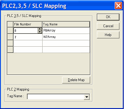
- From the Main Menu, click on Logic and select Map PLC/SLC Messages as shown below.
- The Mapping window shown below opens.
- Choose the file number that you want (7 as in N7:0, etc…).
- Choose the corresponding array.
- Download these changes to the controller and you should see your Data updating.
- When finished, click OK to close the window.