Omron FINS (CS/CJ) Serial Protocol Setup |
Topic:
CM247 |

The following information applies only to the Omron FINS Protocol Series CS and CJ PLC compatible with C-more Panels.
The C-more panel is the master by default.
C-more Protocol Manager Settings
- Do one of the following:
- Click the Protocol Manager button on the Home tab
— or — - Click the Protocol Manager button on the Setup tab
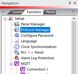
— or — - from the Navigation window, click the Function tab, click Setup and then select Protocol Manager.
- From the Protocol Manager window, click the Device name on the tree to the left.
- The Device Setup window opens.
- From the PLC Protocol
field, click on the down arrow
 and select
Omron CS/CJ FINS Serial.
and select
Omron CS/CJ FINS Serial.
When you select a different PLC Protocol than the one currently in use, the warning Message shown below appears.
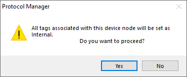
- Click Yes to accept.
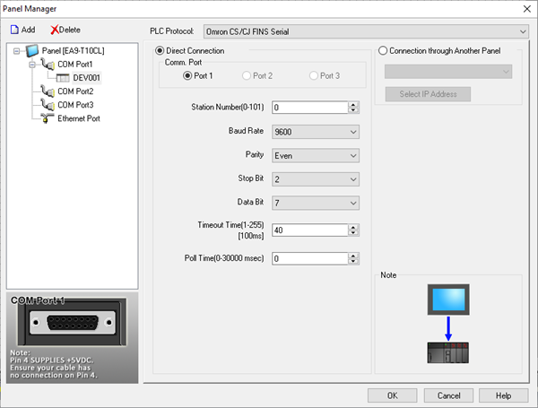
- Complete the fields on the screen using the information in the table below.
Protocol Settings
The C-more Panel Manager Configuration fields for the Omron FINS Protocol for CS and CJ PLC are shown above. From this window you will configure the parameters necessary for proper operation with a C-more Panel.
The fields available for configuration are set by default by the C-more Touch Programming Software but can be modified if needed. Always remember that the field values MUST match the field values on the CX-Programmer Software setup explained later in this topic.
| Panel Manager | |
|---|---|
| Field | Description |
| Station Number (0-101): | The Station Number is the Slave Number or Address. This is the number that will be polled by the C-more Panel. Typically this is set to 1 for the first Slave in the network. Slaves can be addressed from 1 through 101 for Omron FINS, depending on the slave and the CPU used. |
| Baud Rate | The speed or rate at which the Data will be transmitted. It is measured in Bits Per Second (BPS). Both the Panel and the PLC have to be set to the same Baud Rate to be able to communicate. You may choose 9600, 19200, or 38400. |
| Parity | Choose Even, Odd or None for error checking. |
| Stop Bit | Choose 1 or 2 Stop Bits. |
| Data Bit | Data Bits are the portion of the Bit stream that contains useful information for the receiving device. Select either 7 or 8, keeping in mind that the PLC will have to be set the same as the C-more Panel Manager setting. |
| Time-out Time (1-255) | Enter a number that represents a Time in Tenths of a Second that the C-more Panel will wait for communications with the PLC before displaying an error. (Our example uses the default of 40, which is the same as 4000 msec or 4 seconds). |
| Poll Time (0-30000 msec) | Enter a number that represents a Time (in milliseconds) that the C-more Panel will wait between executing a complete sequence of reads for the screen displayed. This setting is set to 0 by default, which produces constant Polling. |
Omron CPU Connection
- From the Main GUI screen, select Settings on the left side explorer bar as shown below. The PLC Settings screen will open.
- From this screen, select the Host Link Port tab. The window will show the settings below. This is the setup for the 9-pin Dsub Port.
- Complete the fields on the Host Link Adapter tab using the information in the table below.
| Host Link Adapter Tab | |
|---|---|
| Field | Description |
| Custom | Under Communications Settings, select Custom. |
| Baud Rate | Match the Baud Rate the C-more Panel Manager. |
| Format | Match the Parity, Stop Bit, and Data Bit in C-more Panel Manager. |
| Mode | Click the drop-down arrow and select Host Link. |
| Unit Number | Click the drop-down arrow and match the unit number to the Station Number Entry in the C-more Panel Manager. |
|
|
Note: The DIP switch 5 on the CPU will set the CPU9 Pin Serial Port to fixed settings. In order for the changes made to the Host Link Port to work, the DIP switch 5 MUST be turned Off. Power cycle the Omron PLC after changing port settings. |
