Allen-Bradley Generic EtherNet/IP Explicit Messaging Setup |
Topic: CM211 |
The following information applies for Allen-Bradley PLC for the purpose of setting up Explicit Messaging via EtherNet/IP. This setup applies only to:
- ControlLogix 1756-EBNT and 1756-ENET/B
- CompactLogix with Built-in EtherNet/IP
The C-more panel is a SLAVE when communicating via Allen-Bradley EtherNet/IP Server (Generic IO Messaging) (Control/CompactLogix).
C-more Protocol Manager Settings
- Do one of the following:
- Click the Protocol Manager button on the Home tab
— or — - Click the Protocol Manager button on the Setup tab
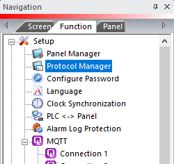
— or — - from the Navigation window, click the Function tab, click Setup and then select Protocol Manager.
- From the Protocol Manager window, click the Device name on the tree to the left.
- The Device Setup window opens.
- From the PLC Protocol field, click on the down arrow
 and select Allen-Bradley EtherNet/IP Server (Generic IO Messaging) (Control/CompactLogix MSG).
When you select a different PLC Protocol than the one currently in use, the warning Message shown below appears.
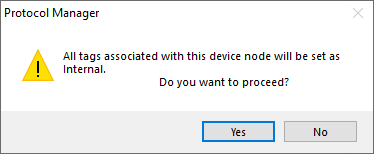
- Click Yes to accept.
All settings must be set the same as the settings in Protocol Manager in the C-more Programming Software. The C-more Protocol Manager is shown above with the Generic EtherNet/IP driver selected.
Setup Explicit Messaging
We will not attempt to outline all of the specific instructions to set up Explicit Messaging via EtherNet/IP. EtherNet/IP is generic and can be used with many different platforms. The important part is to use the correct EtherNet/IP Service, Class, Instance and Attribute. The ControlLogix and CompactLogix MSG (Message) instructions are included below. These instructions show the correct codes to use for Explicit Messaging to the C-more panel.
- The first thing to do in the ControlLogix and CompactLogix is to create an MSG instruction.
- Give the MSG a Name. In the sample below MSG Name is CmorePanelRead.
- Declare this name as a Message Data Type. To do this, right-click on the name and select the name just given.
- The New Tag dialog box for declaring the Data Type for the MSG instruction name will open. Select Message for the Data Type field and select (Controller) for the Scope field. Click on the OK button to accept changes and close the New Tag window.
-
Now click on the three dots button next to the Data Type field. The Message Configuration dialog box shown below opens. This box is discussed in the section below.
Configuration Tab
Message Configuration Dialog Box Setup — Configuration Tab
To configure the Message to read the Input Data from the C-more Panel:
- Select Service Type 0x0e which is Get Attribute Single.
- Enter Class 0xa0 (a0).
- Enter Instance 0x01 (1).
- Enter Attribute 0x01 (1).
The PLC's Destination Array (or Data File in other PLC), which is DataRead in the figure shown above, needs to be sufficiently large to accommodate all of the Input Data in the Panel that is set up through the C-more Panel Manager Maximum Input Field.
Be sure that the array you create is an Integer (INT) Data Type.
|
|
Note: This value is expressed in Bytes in RSLogix but in Words in the C-more Panel Manager. Be sure that the array you create is an Integer (INT) Data Type. |
Configuration Tab — Read Output Data from the C-more Panel
To configure the Message to read the Output Data from the C-more panel:
- Select Service Type 0x0e, which is Get Attribute Single.
- Enter Class 0xa1 (a1).
- Enter Instance 0x01 (1).
- Enter Attribute 0x01 (1).
|
|
Note: This value is expressed in Bytes in RSLogix but in Words in the C-more Panel Manager. Be sure that the array you create is an Integer (INT) Data Type. |
Configuration Tab — Write Output Data to the C-more Panel
To configure the Message to write the Output Data to the C-more Panel:
- Select Service Type 0x10, which is Set Attribute Single.
- Enter Class 0xa1 (a1).
- Enter Instance 0x01 (1).
- Enter Attribute 0x01 (1).
The PLC Source Element (or Data File in other PLC), which in the figure shown above is WriteBuffer, needs to be sufficiently large to accommodate all of the Output Data in the Panel that is setup through the C-more Panel Manager's Maximum Output Field.
|
|
Note: This value is expressed in Bytes in RSLogix but in Words in the C-more Panel Manager. Be sure that the array you create is an Integer (INT) Data Type. |
Communication Tab
Message Configuration Dialog Box Setup — Communication Tab
To Define the Port being used on the PLC (Ethernet Port on PLC CPU in ControlLogix and Ethernet card in ControlLogix) to communicate to the Panel. You also define the IP Address of the panel in this window.
- Click on Browse to choose the Ethernet port of the PLC that you are using.
- Choose the Ethernet card you are using and select OK.
- Enter a comma after the Ethernet card (LocalENB, ).
- Enter the Port Number of the Ethernet card you are using (LocalENB,2).
- For CompactLogix with the built in Ethernet Port, enter 2. For ControlLogix with an Ethernet card, enter 2 as well.
- Enter another comma and then the IP Address of the panel you are connecting to (LocalENB,2,10.1.33.25). Be sure to put the period between the IP Address Octets.