FANUC R-30iB Addressing and Mapping |
Topic: CM121 |
Caution: Only someone familiar with Fanuc Robot Controllers should update these settings.
|
ROBOT I/O SIGNAL |
FANUC ADDRESS |
HMI ADDRESS |
EXAMPLE |
|---|---|---|---|
| Digital Input | DI[x] | %Qx | DI[1] ⇔ %Q1 |
| Digital Output | DO[x] | %Ix | DO[1] ⇔ %I1 |
| Robot Input | RI[x] | %Q(5000+x) | RI[1] ⇔ %Q5001 |
| Robot Output | RO[x] | %I(5000+x) | RO[1] ⇔ %I5001 |
| UOP Input | UI[x] | %Q(6000+x) | UI[1] ⇔ %Q6001 |
| UOP Output | UO[x] | %I(6000+x) | UO[1] ⇔ %I6001 |
| SOP Input | SI[x] | %Q(7000+x) | SI[0] ⇔ %Q7001 |
| SOP Output | SO[x] | %I(7000+x) | SO[0] ⇔ %I7001 |
| Weld Input | WI[x] | %Q(8000+x) | WI[0] ⇔ %Q8001 |
| Weld Output | WO[x] | %I(8000+x) | WO[0] ⇔ %Q8001 |
| Wire Stick Input | WSI[x] | %Q(8400+x) | WSI[0] ⇔ %Q8400 |
| Wire Stick Output | WSO[x] | %I(8400+x) | WSO[0] ⇔ %Q8401 |
| Group Input | GI[x] | %AQx | GI[1] ⇔ %AQ1 |
| Group Output | GO[x] | %AIx | GO[1] ⇔ %AI1 |
| Analog Input | AI[x] | %AQ(1000+x) | AI[1] ⇔ %AQ1001 |
| Analog Output | AO[x] | %AI(1000+x) | AO[1] ⇔ %AI1001 |
| PMC Keep Relay |
DO[x] (x : 10001 – 10144) Ka.b |
%Ix %I((a*8)+b+10001) |
DO[10001] ⇔ %I10001 K2.5 ⇔ %I10022 |
| PMC Internal Relay |
DO[x] (x : 11001 – 23000) Ra.b |
%M(x-11000) %M((a*8)+b+1) |
DO[11001] ⇔ %M1 R2.5 ⇔ %M22 |
| PMC Data Table |
GO[x] (x : 10001 – 12000) D(a*2), D((a*2)+1) |
%AI(x-6000) %AI(a+4001) |
GO[10001] ⇔ %AI4001 D4, D5 ⇔ %AI4003 |
|
|
Note: Meanings of the robot controller signals are opposite to those of the C-More signals. Example: robot controller input signals correspond to %Q and %AQ and output signals correspond to %I and %AI. |
|
ROBOT DATA |
FANUC ADDRESS |
HMI ADDRESS |
EXAMPLE |
|---|---|---|---|
| Register | R[x] | %Rx | R[1] <=> %R1 |
Values in registers are Signed Int 16 numbers, the fractional part is rounded off.
Register values must be between -32768 and 32678 to be read correctly.
Change this standard mapping with the $SNPX_ASG system variable. With this system variable, you can set up a multiplier to convert and modify register mapping. You can map one register to one %R variable as a Signed Int 16.
By default register mapping is related to $SNPX_ASG system variable settings, as follows:
|
NAME |
VALUE |
|---|---|
| $ADDRESS | 1 |
| $SIZE | 10000 |
| $VAR_NAME | 'R[1]@1.1' |
| $MULTIPLY | 1.000 |
With these settings, the registers R[1] through R[10000] are addressed to %R1 through %R10000 as Signed Int 16.
|
$SNPX_ASG ELEMENT |
EXPLANATION |
|---|---|
| $ADDRESS | Start address of %R |
| $SIZE | Number of %R’s to be assigned |
| $VAR_NAME | String indicating the data to be assigned consecutively |
| $MULTIPLY | Because C-More only addresses Signed Int 16 numbers this must remain 1.00 |
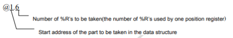
The @ symbol in $VAR_NAME denotes how many Registers will be used for the data. Example: 'R[1]@1.1' means your first register (R[1]) will be written to the start location (@1) and will use one %R (.1) that will be used by each register.
|
|
Note: Other address mappings can be accomplished using $SNPX_ASG. Please refer to Fanuc Manuals for further information. |
