AutomationDirect Modbus (DL05/06/205/350/405) Protocol Setup |
Topic: CM102 |
Use the AutomationDirect Modbus (Koyo Addressing) protocol with Direct LOGIC PLC DL05 (all models), DL06 (all models), D2-250, D2-250-1, D2-260, D3-350 and D4-450.
|
|
Note: The PLC Mode Switch must be in (TERM) position in order for the C-more Panel to communicate with the PLC. Refer to the specific PLC user manual for further details. These manuals are available online and for download at www.automationdirect.com. |
These PLC support ladder program multilevel Password protection.
This allows password protection without locking the communication port to an operator interface.
To invoke Multilevel Password, create a password with an uppercase 'A" followed by seven numeric characters (e.g., A1234567). Refer to the specific PLC user manual for further details. These manuals are available online and for download at www.automationdirect.com.
C-more Protocol Manager Settings
- Do one of the following:
- Click the Protocol Manager button on the Home tab
— or — - Click the Protocol Manager button on the Setup tab
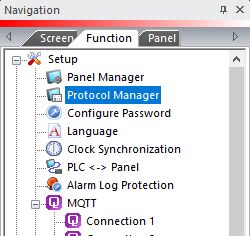
— or — - from the Navigation window, click the Function tab, click Setup and then select Protocol Manager.
- From the Protocol Manager window, click the Device name on the tree to the left.
- The Device Setup window opens.
-
Click on the PLC Protocol drop down and select AutomationDirect Modbus (DL05/06/205/350/405).
- You can add more device drivers in the Protocol Manager dialog box by right clicking on the port and selecting New.
- Make sure that the protocol in the Panel Manager matches the setup of the PLC communications port which follows.

PLC Protocol Settings
a. PLC Slave Number (1-247)
The Node Address of the PLC port. Match the Node Address field for Port 2 of the PLC port connected to the C-more panel. If the C-more panel is connected to Port 1 of the PLC, this number is 1.
b. Baud Rate
Match the Baud Rate set in the Baud Rate field for Port 2 of the PLC port. If the C-more panel is connected to Port 1 of the PLC, this number is 38400.
c. Parity
A low-level form of error check that counts the occurrences of the number 1 in the bit stream to ensure that none has changed.
Parity is configured to count the correct occurrences of the number 1 in the Data packet: odd or even.
If the occurrences of the number 1 is even when parity is set to odd, the packet is corrupted.
Odd is the default and should not require adjustment.
d. Stop Bit
Extra bits which follow the data and parity bits to mark the end of the transmission. For older systems, you may need to increase the Stop Bit to 2, but 1 (the default) is usually the correct setting.
Match the Stop Bit selection configured in Parameter P9.02.
e. Control RTS
Choose Yes for the C-more panel to sense if the RTS signal line is controlled from the PLC port.
Select Yes if the RS-422 driver signal is turned OFF at the end of transmission. The default is No, based on connecting to a port with the RTS and CTS signals jumpered together.
f. Require CTS
Select Yes in this drop-down if using a modem on the C-more serial port for flow control. Otherwise, leave this setting at No.
g. Select RS 485
Select Yes in this drop-down if you need 2-wire RS 485 communication. The default is No, based on connecting to a port with the RTS and CTS signals jumpered together.
When you select Yes in this field, you must jumper the SD+ and RD+ along with the SD- and RD- pins. On is the default since the GS Drives use 2 wire RS-485 as their method of serial communication.
h. PLC Protocol
RTU is set and you cannot change it for this Protocol.
i. Registers Per Message
The number of registers to read/write per message. The default number is 64. Choose fewer registers per message to reduce the communication time for a single message and increase the amount of error checking.
Adjust this number for specific controllers with a limited register allowance in a Read or Write Message.
j. Coils Per Message
The number of coils to read/write per message. The default number is 64. Choose fewer coils per message to reduce the communication time for a single message and increase the amount of error checking.
Adjust this number for specific controllers with a limited coil allowance in a Read or Write Message.
k. Timeout time (1-255) [100 msec]
The time (in 100 millisecond increments) the C-more Panel waits for communications with the PLC before it displays an error. 30 tenths of a second (3 seconds) is the default and should not require adjustment.
l. Poll Time (0-30000) [msec]
Setup PLC Comm Port for AutomationDirect Modbus (JTEKT Addressing) with DirectSoft
- In the DirectSOFT programming software, from the main menu, click the PLC drop-down, click Setup, then click Setup Sec. Comm Port.
- The Setup Communication Ports window opens.
- Set the protocol settings as shown below.
- These settings should match those in the C-more Protocol Manager.
a. Time-out
The amount of time the port waits for a response to a message before it logs an error.
It is only used when the PLC is the Master device.
This is relative to the Base Time-out listed next to each protocol, i.e. for Modbus, Base Time-out x 1 = 500 ms. (In our example, we have kept the default of 500 ms.)
b. RTS (Request to Send)
A handshaking signal to notify another device that the asserting device would like to transmit.
RTS ON and RTS OFF delay can typically be set to 0 ms for 4-wire networks.
For 2-wire networks, the values should be increased to 5 ms and 2 ms respectively.
c. Station Number
The Slave Number or Address.
This is the number polled by the Master on the network.
Typically, this is set to 1 for the Master. Slaves can be addressed from 1 through 90 for Direct NET protocol or 1 through 247 for Modbus protocol, depending on the Slave and CPU. (The example uses the default Station Number 1.)
d. Baud Rate
The connection transmit speed in Bits Per Second (bps).
A good starting point is 9600 bps. If there are no problems, increase the Baud Rate to the maximum without communication problems.
e. Stop Bit
Extra bits which follow the data and parity bits to mark the end of the transmission. For older systems, the Stop Bit may need to be increased to 2, but 1 is usually the correct setting. (The example uses a default Stop Bit of 1.)
f. Parity
A low-level form of error checking that counts the occurrences of the number 1 in the bit stream to ensure that none has changed.
Parity is configured to count the correct occurrences of the number 1 in the Data packet: odd or even.
If the occurrences of the number 1 is even when parity is set to odd, the packet is corrupted.
Odd is the default and should not require adjustment.
g. Echo Suppression
In a Half Duplex 2-wire network, the transmit device receiver must be disabled so that data is not echoed to the receiver.
If you select Modbus as the network protocol, you must select either 4-wire or 2-wire.
In effect, this is turning Echo Suppression ON for 2-wire networks and OFF for 4-wire networks and RS-232.
|
|
Note: The Baud Rate, Stop Bits, and Parity must all be the same for every device on the network in order for communications to work properly. |
