AutomationDirect Do-more Symbolic (Full Memory) |
Topic:
CM053 |
The following devices support the Do-more Serial Symbolic Addressing driver (all Do-more PLC require OS ver. 2.0.2 or later):
- H2-DM1E
- H2-DM1 with H2-ECOM100 (ver. 4.0.1808) communication module
- T1H-DM1E
- BX-DM1E
- BX-DM with the BX-P-ECOMLT communication module
C-more Protocol Manager Settings
- Do one of the following:
- Click the Protocol Manager button on the Home tab
— or — - Click the Protocol Manager button on the Setup tab
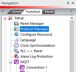
— or — - from the Navigation window, click the Function tab, click Setup and then select Protocol Manager.
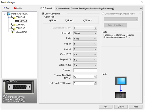
- From the Protocol Manager window, click the Device name on the tree to the left.
- The Device Setup window opens.
- In the PLC Protocol field, select AutomationDirect Do-more Serial Symbolic Addressing.
When you select a different PLC Protocol than the one currently in use, the warning Message shown below appears.
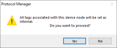
- Click Yes to accept.
|
|
Note: Connection through another panel is not available using the Do-more driver. |
- Complete the fields on the screen using the information in the table below.
| Panel Manager | |
|---|---|
| Field | Description |
| Baud Rate | Match this setting to match the Baud Rate setting in the Do-more CPU serial port configuration. |
| Parity | Match this setting to match the Parity setting in the Do-more CPU serial port configuration. |
| Stop Bit | Match this setting to the Stop Bit setting in the Do-More CPU serial port configuration. This value is most often 1. |
| Data Bit | Match this setting to match the Data Bit setting in the Do-More CPU serial port configuration. This value is most often 8. |
| Control RTS | If you select Yes in this field, C-more asserts the serial port RTS signal before transmitting data. This signal is commonly used with media converters such as FA-ISOCON. |
| Control FTS | If you select Yes in this field, C-more checks to see if the CTS signal is asserted from the connected device before it transmits data. |
| Select RS 485 | Select Yes for this field if you need 2 wire RS-485 communications. Along with selecting Yes in this field, you must jumper the SD+ with the SD- and RD- pins. |
| Password | If the Do-more CPU is configured to use a password, the project needs to store this password to communicate with the Do-more. You must enter the password into this field. |
| Timeout Time (0-40) (in 100ms units) | The amount of time (in 100 ms increments) that the panel waits on a reply after sending a request. |
| Poll Time | The amount of time (in milliseconds) that the panel waits in between each request. |
|
|
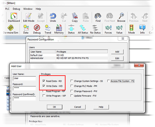
Note: You must configure the Do-more password to allow access privileges for other devices. The minimum privileges Read Data: RD and Write Data: WD selected to work correctly with C-more. |
Serial Port Settings Using Do-more Designer
- Once you connect the Do-more CPU with Do-more Designer software, click the Configure button in the toolbar.
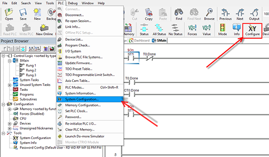
- The System Configuration dialog box opens. Set the Serial Port Configuration to Do-more Programming.
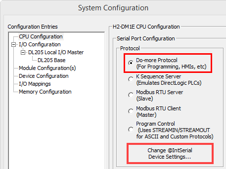
- Click the @IntSerial Device Settings button to set the other serial port options.
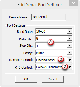
- Baud Rate, Data Bits, Stop Bits, and Parity: must match the C-more Programming Software Panel Manager setup described.
- Transmit Control: set to Unconditional (RS232) or Delayed 5ms (RS-485).
- RTS Control: set to Follows Transmitter.
